Electric toothbrush

a toothbrush and electric technology, applied in the field of electric toothbrushes, can solve the problems of hardly matching the optimum value of the brush angle, few users are conscious of the desired brush angle, and the mechanism disclosed in the patent document 1 is hardly miniaturized and implemented, so as to achieve the effect of convenient realization

Active Publication Date: 2013-01-01
OMRON HEALTHCARE CO LTD
View PDF12 Cites 21 Cited by
  • Summary
  • Abstract
  • Description
  • Claims
  • Application Information

AI Technical Summary

Benefits of technology

[0020]According to the present invention, the proper brush angle can easily be realized in the electric toothbrush.

Problems solved by technology

However, few users are conscious of the desired brush angle.
Even if the user is conscious of the brush angle, because the user cannot confirm a state in which the brush abuts actually on the teeth during the brushing of teeth, the brush angle is hardly matched with the optimum value.
However, the mechanism disclosed in Patent Document 1 is hardly miniaturized and implemented.

Method used


Image

  • Electric toothbrush
  • Electric toothbrush
  • Electric toothbrush

Examples


first embodiment

Configuration of Electric Toothbrush

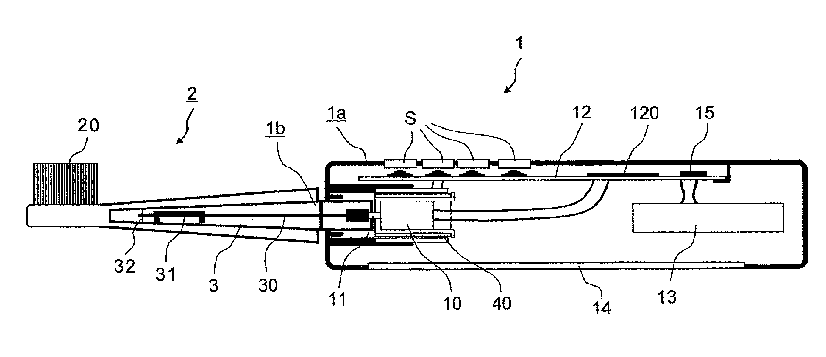
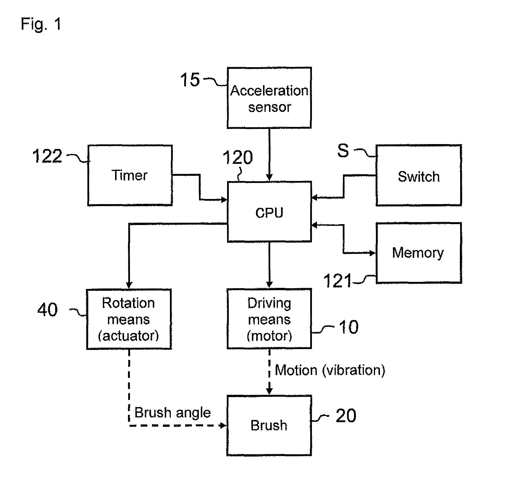
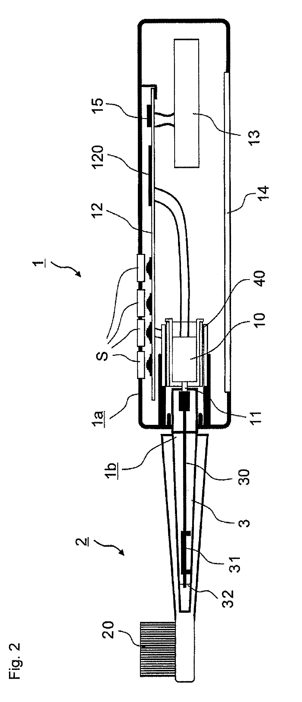
[0045]A configuration of an electric toothbrush will be described with reference to FIGS. 1, 2, and 3. FIG. 1 is a block diagram of the electric toothbrush of the first embodiment, FIG. 2 is a sectional view illustrating an internal configuration of the electric toothbrush of the first embodiment, and FIG. 3 is a perspective view illustrating an appearance of the electric toothbrush.

[0046]The electric toothbrush includes an electric toothbrush main body 1 (hereinafter simply referred to as the “main body 1”) and a brush member 2. The main body 1 includes an outer chassis 1a and an inner chassis 1b. The brush member 2 is attached to the inner chassis 1b of the main body 1.

[0047]The outer chassis 1a of the main body 1 is formed by a resin case having a substantially cylindrical shape. An elastomer grip portion 14 and a switch S are provided in the outer chassis 1a. The grip portion 14 is held with a hand of a user in brushing the teeth. The switch S...

second embodiment

[0087]FIG. 15 illustrates a configuration of an electric toothbrush according to a second embodiment of the present invention. The second embodiment differs from the first embodiment in that a bearing 44 is provided between the outer chassis 1a and the inner chassis 1b. With this configuration, position stability of the inner chassis 1b is improved. Because the position of the inner chassis 1b is stabilized, a length in the axis direction of the actuator 40 can be shortened, thereby contributing to miniaturization of the electric toothbrush main body 1.

third embodiment

[0088]FIG. 16 illustrates a configuration of an electric toothbrush according to a third embodiment of the present invention. In the first and second embodiments, the electric power is supplied to the motor 10 through a lead wire. On the other hand, in the third embodiment, the electric power is supplied to the motor 10 from the driving circuit 12 through an electric connection unit 45.

[0089]In the configurations of the first and second embodiments in which the motor 10 and the driving circuit 12 are connected by the lead wire, it is necessary to restrict the rotation range of the actuator 40 in order to prevent the twist or disconnection of the lead wire. On the other hand, the electric connection portion 45 of the third embodiment has a circuit configuration such that the electric connection is secured between the electric power supply line on the driving circuit and an electrode of the motor 10 irrespective of the rotation angle of the actuator 40. For example, the configuration ...


PUM


Abstract

An electric toothbrush includes an electric toothbrush main body that includes a grip portion; a brush member that includes a brush; a motor that moves the brush; an actuator that relatively rotates the brush member with respect to the electric toothbrush main body in order to change an orientation of the brush; an acceleration sensor that detects an attitude of the main body; and a CPU that controls the actuator such that a brush angle becomes a predetermined optimum value based on the detected attitude.

Description

TECHNICAL FIELD[0001]The present invention relates to an electric toothbrush.BACKGROUND ART[0002]There is well known a type of electric toothbrush in which a brush moving at high speed abut on teeth to perform brushing of teeth (remove a food residue or dental plaque). In such electric toothbrushes, an obtained cleaning effect depends on an angle at which the brush abuts on the teeth. For example, when the brush abuts on a tooth axis at 90 degrees, the highest dental plaque removing force can be exerted with respect to a tooth plane. When the brush abuts on the tooth axis at 45 degrees, a tip of brush invades easily into an interdentium or a periodontal pocket (between tooth and gum-ridge), and the food residue or the dental plaque can effectively be scraped out from the interdentium or the periodontal pocket.[0003]Thus, there is an optimum brush angle (angle of the brush with respect to the tooth axis) according to a brushing region or the desired cleaning effect. However, few user...

Claims


Application Information

Patent Timeline
Patent Type & Authority Patents(United States)
IPC IPC(8): A61C17/22
CPCA46B15/0006A61C17/221A61C17/3481
Inventor IWAHORI, TOSHIYUKI
Owner OMRON HEALTHCARE CO LTD
Why Eureka
Try Eureka