Apparatus and methods for continuous compatibility testing of subterranean fluids and their compositions under wellbore conditions
a technology of fluid compatibility and apparatus, applied in the field of apparatus and methods for continuous compatibility testing of subterranean fluids and their compositions under wellbore conditions, can solve the problems of fluid compatibility and material in some mixtures being characterized as incompatibl
- Summary
- Abstract
- Description
- Claims
- Application Information
AI Technical Summary
Benefits of technology
Problems solved by technology
Method used
Image
Examples
example a
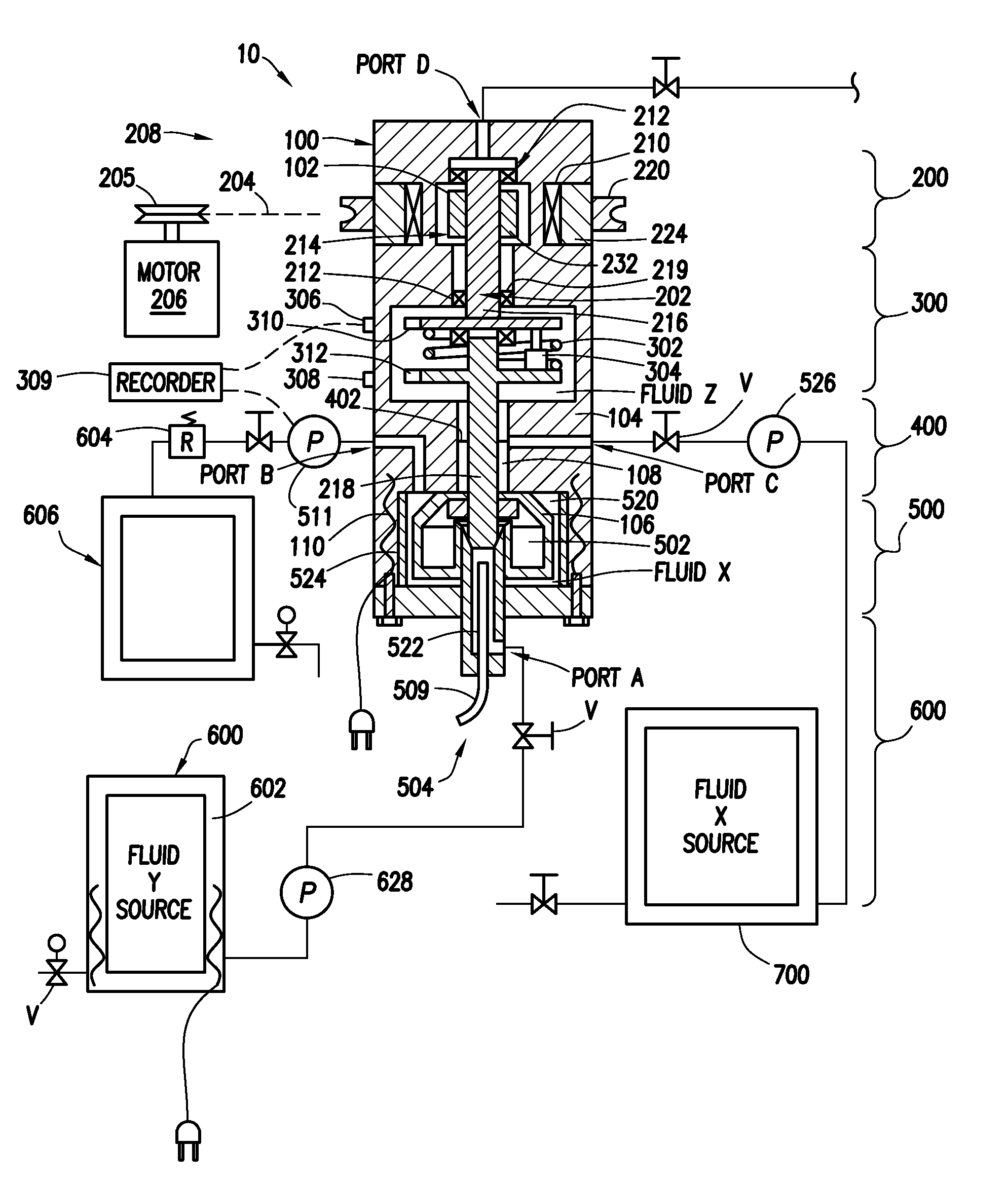
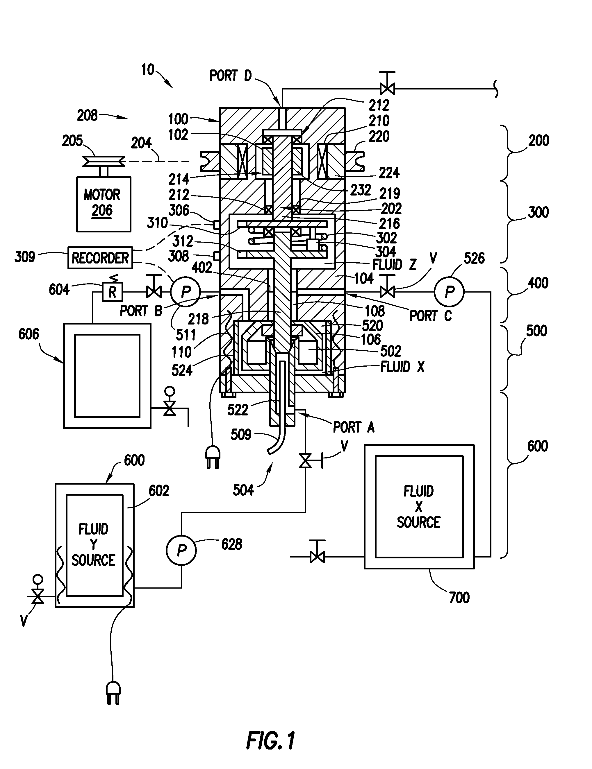
[0033]An example of a method of utilizing the test apparatus 10 will be described in reference to FIG. 1 and is illustrative of the present invention used to test a variety of proportional mixtures of test fluids and / or solids X and Y. Hydrocarbon well application examples of components of mixtures to be tested include hydrocarbon liquids and gases, acids, gels, cement, mud, proppant, sand, bauxite spacers and elastomers, clays, slag, fly ash, surfactant, polymers and the like. For example, slurries of proppant from 8 to 100 mesh can be tested. In this example, two fluids in liquid form are tested, however, a variety of proportional mixtures and slurries of two or more fluids and solids could also be tested. Indeed a single fluid could also be tested under different conditions using the present inventions.
[0034]The first step in this example is to manipulate the valves v and pump 526 to inject fluid X from reservoir assembly 700 into the lower chamber portion 106 through Port C. Inj...
example b
[0042]The testing apparatus can also be used to perform a series of tests of samples of well fluids. In this example, the reservoir assembly 600 is connected to a source of well fluids such as, for example, the drilling mud which at the time was being circulated through the well. As in example A, the ports are used to place a first test sample in the lower chamber portion 106. As described in Example “A” using the ports, a suitable second fluid is placed above the test fluid and the contents of the enclosure are brought to test conditions. The test fluid is then tested. When it is desired to test a second test sample, the second sample is pumped into the lower chamber portion 106 by displacing the first sample and to discharge it from the apparatus into waste reservoir 606. The fluids remaining in the lower chamber 106 will approach, but not completely reach, a 100% concentration of the second sample. The second sample is then tested. This process can be repeated with succession of ...
example c
[0043]The apparatus can also be used to perform continuous monitoring (testing) of a fluid as it is pumped through the lower chamber portion by pump 526. For example, a fluid being pumped into or circulated through a wellbore (or other fluid application) could be continuously sampled and the sample pumped through the lower chamber. With the motor running, the shear forces are constantly measured and recorded along with the temperature and pressure. Ideally, a pressure regulator 604 is connected to the discharge port to maintain the test pressure while the test fluid is being circulated through the lower chamber.
[0044]After the test is completed the lower chamber portion 106 is disassembled and the removable cylindrical cup 524, vanes 520 and rotating paddle assembly 502 are removed and cleaned.
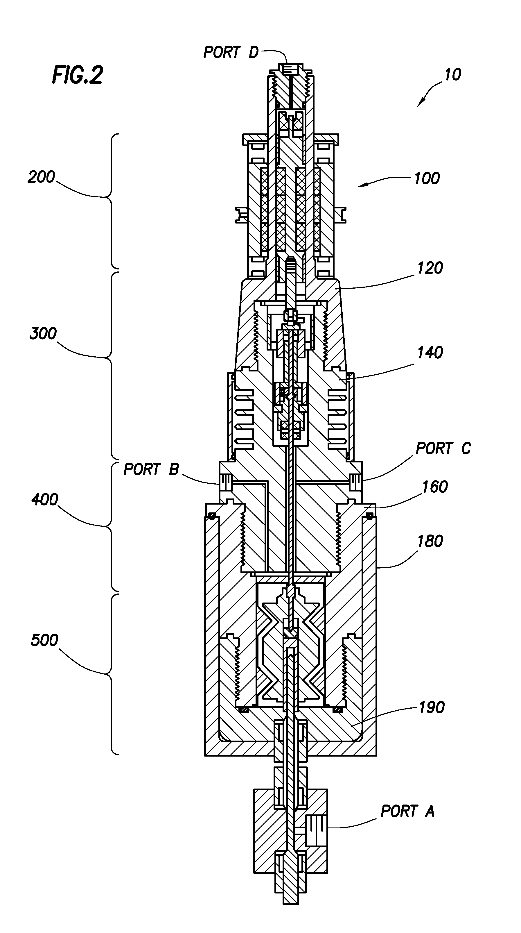
[0045]Turning now to FIG. 2, the details of another embodiment of the testing apparatus 10 will be described. In this embodiment, the pressure chamber housing assembly 100 is made up of an upp...
PUM
| Property | Measurement | Unit |
|---|---|---|
| pressure | aaaaa | aaaaa |
| pressures | aaaaa | aaaaa |
| temperatures | aaaaa | aaaaa |
Abstract
Description
Claims
Application Information
 - R&D
- Intellectual Property
- Life Sciences
- Materials
- Tech Scout
- Unparalleled Data Quality
- Higher Quality Content
- 60% Fewer Hallucinations
Browse by: Latest US Patents, China's latest patents, Technical Efficacy Thesaurus, Application Domain, Technology Topic, Popular Technical Reports.
© 2025 PatSnap. All rights reserved.Legal|Privacy policy|Modern Slavery Act Transparency Statement|Sitemap|About US| Contact US: help@patsnap.com


