
Headgear for mounting surgical headlight

a headgear and headlamp technology, applied in the field of surgical headlight systems, can solve the problems of interrupting the surgical procedure, distracting the surgeon, and having to wear the headgear and headlamp continuously,

Active Publication Date: 2013-01-08
SUNOPTIC TECH
View PDF22 Cites 35 Cited by
  • Summary
  • Abstract
  • Description
  • Claims
  • Application Information

AI Technical Summary

Problems solved by technology

A surgeon may be required to continuously wear the headgear and headlamp for many hours during the course of delicate or complicated surgery.
Such events may distract the surgeon and possibly interrupt the surgical procedure.
However, such tightening typically leads to discomfort which also may be distracting to the surgeon.

Method used


Image

  • Headgear for mounting surgical headlight
  • Headgear for mounting surgical headlight
  • Headgear for mounting surgical headlight

Examples


Embodiment Construction

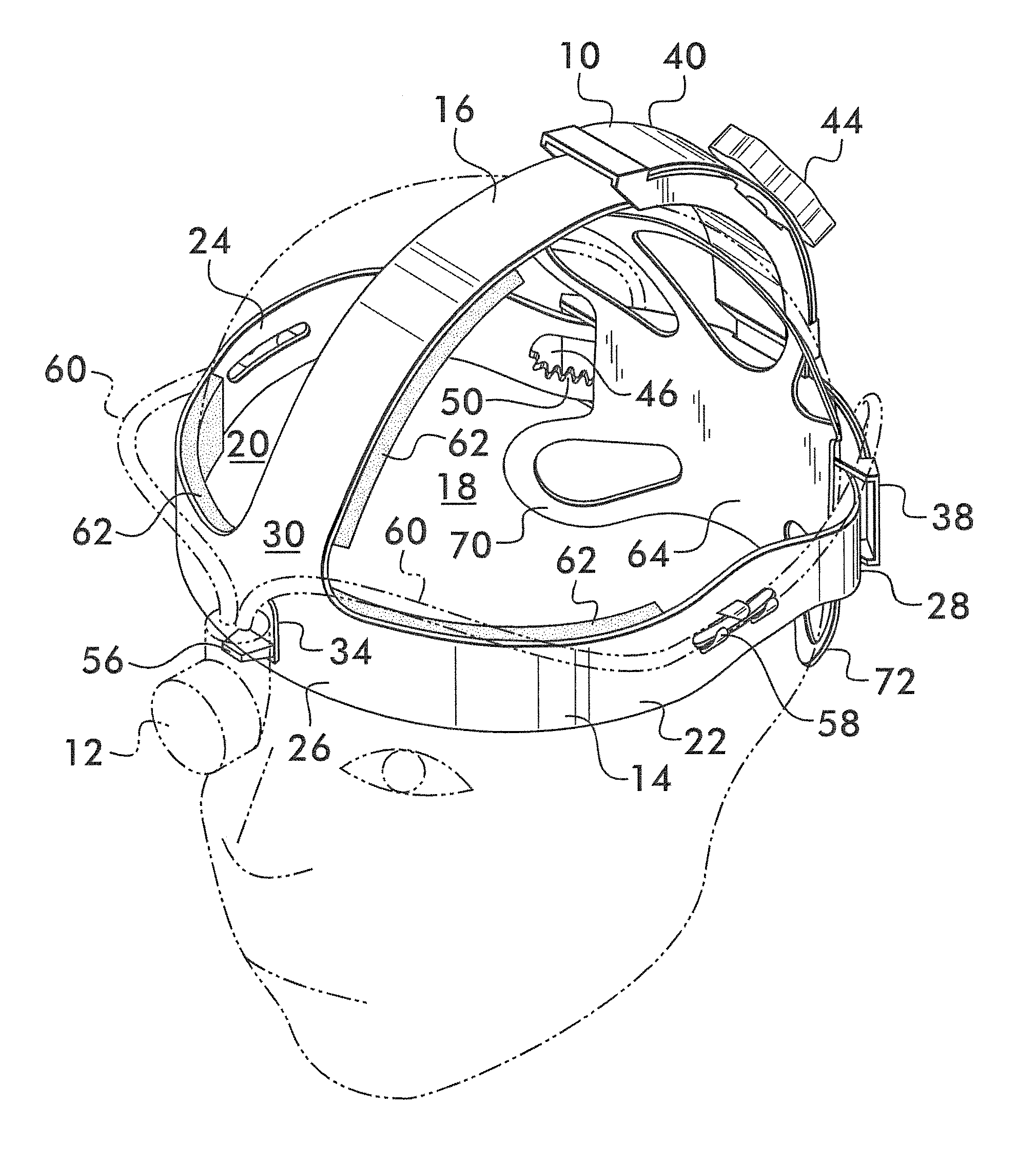
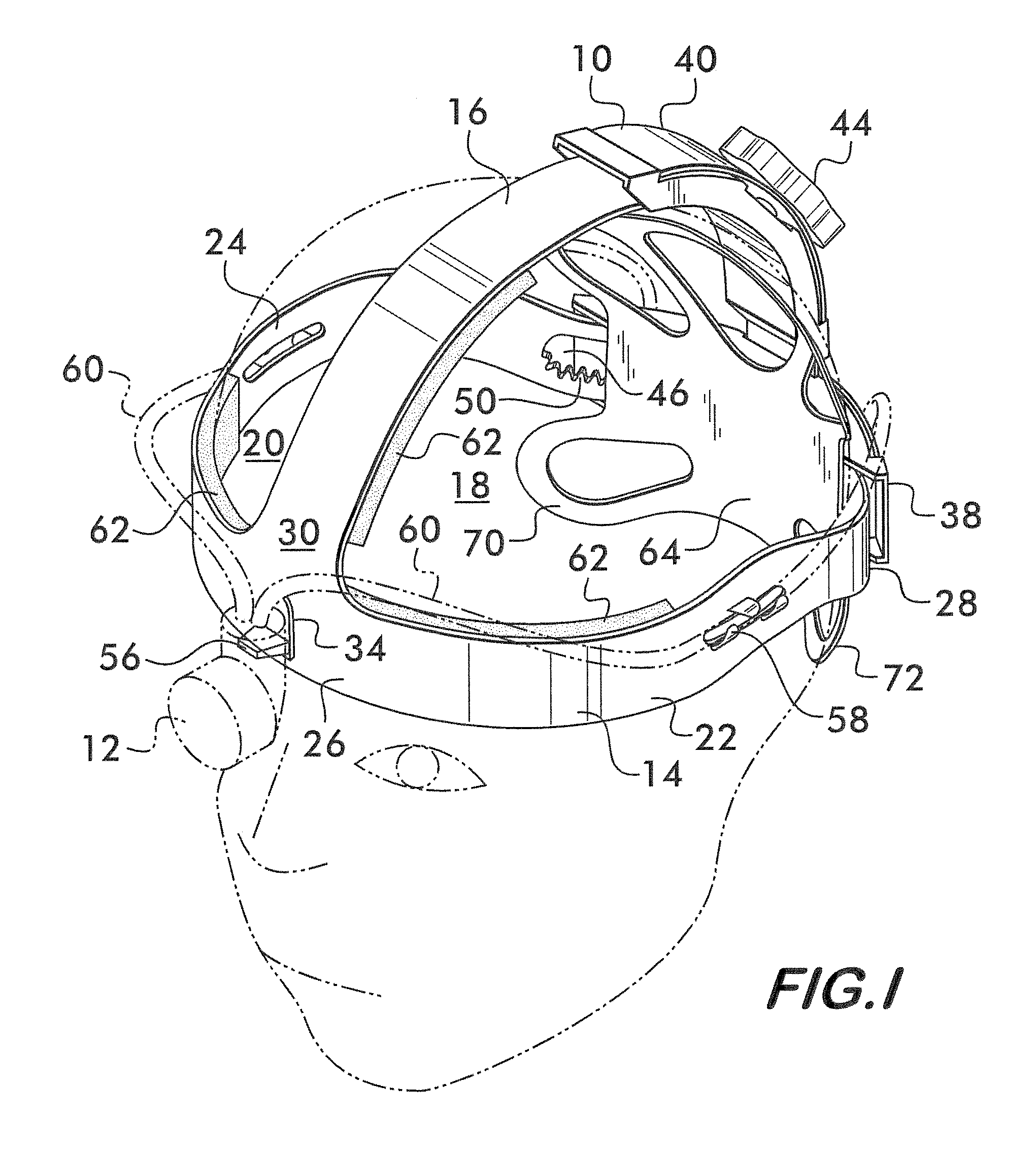
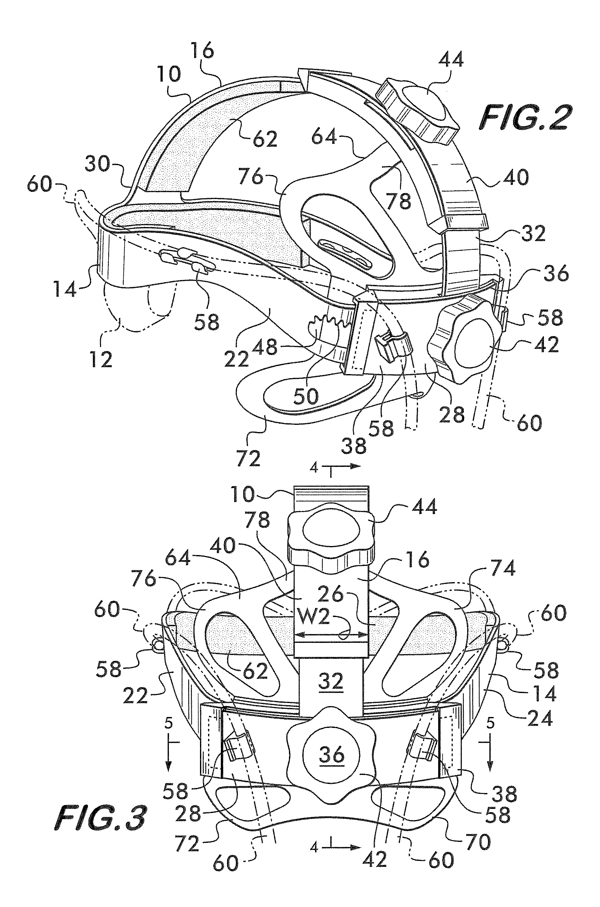
[0018]The headgear 10 of the present invention provides a means for mounting a headlamp 12 or the like in a desired position on the head of a surgeon or other wearer. Typically, the headlamp 12 will be mounted to the headgear 10 such that it extends downwardly and forwardly from a location corresponding generally to the front and center of the forehead of a surgeon or other wearer of the headgear 10. The headgear 10 of the present invention has means for providing improved stability when the headgear 10 is worn while also maximizing comfort. Accordingly, there is no need to tighten or over-tighten the headgear 10 of the present invention on the head to an extent that causes discomfort to the wearer.

[0019]The headgear 10 has a generally openwork construction such that it is lightweight and does not trap or inhibit the transfer of heat from the wearer's head or inhibit the majority of the head to be exposed to ambient conditions. Thus, when the headgear 10 is worn, the majority of the...


PUM


Abstract

Headgear for mounting a headlight on a surgeon's head includes a headband and a stabilizer. The headband encircles the wearer's head and the stabilizer is connectable to a rear section of the headband for engaging and cradling a substantial portion of at least a lower back region of a wearer's head when the headgear is worn by the wearer. The stabilizer includes a peripheral extending portion extending beneath the headband on opposite sides of the wearer's head corresponding to a location of a lower portion of an occipital bone of the wearer's head and a peripheral portion extending above the headband on opposite sides of the wearer's head corresponding to a location of a top of the occipital bone. The headgear can also include a connection element for removably connecting the stabilizer to the headband so that the headgear can be worn with or without the stabilizer.

Description

BACKGROUND OF THE INVENTION[0001]The present invention relates to surgical headlight systems, and more particularly, the present invention relates to headgear for mounting headlights on the head of a surgeon.[0002]Headlights are worn on the head of surgeons, technicians, and like individuals for directing a spotlight beam of intense light coincident with the wearer's line of sight, independent from overhead and / or ambient lighting. Headlight systems typically include a headlamp that receives an emitting end of a fiber optic cable and that focuses and directs the light from the cable into a beam aimed forward of the wearer. The headlamp includes an assembly of optic elements that is preferably configured in a tubular elbow which depends from a headband of headgear at the wearer's forehead to a location approximately between the wearer's eyes.[0003]An example of a headlight system is disclosed by U.S. Pat. No. 7,314,300 B1 issued to Don et al. which is assigned to Sunoptic Technologie...

Claims


Application Information

Patent Timeline
Patent Type & Authority Patents(United States)
IPC IPC(8): F21V21/08
CPCA42B1/244A61B1/0692A42B3/14
Inventor OROZCO, WALTER ANTONIOHUNTER, JAMES D.
Owner SUNOPTIC TECH
Learn More