Sensing device orientation in wireless networks

a wireless network and sensing device technology, applied in the field of wireless digital networks, can solve the problems of significant signal loss, significant differences in coverage and signal strength,

Active Publication Date: 2013-01-08
HEWLETT-PACKARD ENTERPRISE DEV LP +1
View PDF13 Cites 19 Cited by
  • Summary
  • Abstract
  • Description
  • Claims
  • Application Information

AI Technical Summary

Problems solved by technology

The differences in resulting antenna height and polarization between different mounting types and orientations may result in significant differences in coverage and signal strength.
If for example one node is installed with a vertically polarized antenna and the other node is installed with a horizontally polarized antenna, significant signal loss will result.

Method used


Image

  • Sensing device orientation in wireless networks
  • Sensing device orientation in wireless networks
  • Sensing device orientation in wireless networks

Examples


Embodiment Construction

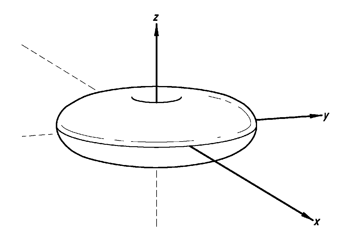
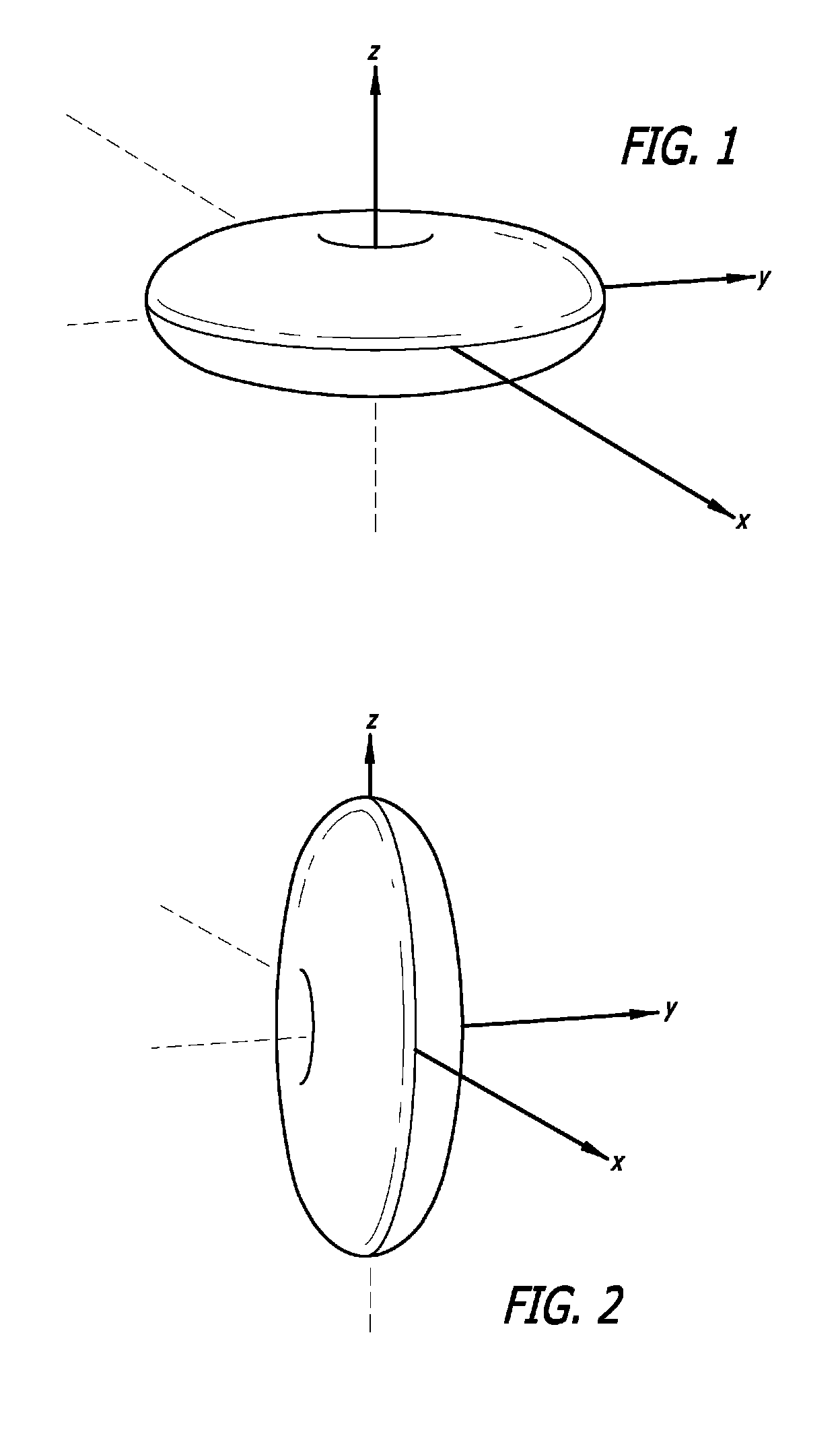
[0015]Embodiments of the invention relate to methods and apparatus for sensing the installed orientation of an antenna or access node in a wireless digital network. An orientation sensor is mounted in the access node, or alternatively, the orientation sensor is coupled to one or more antennas associated with the access node. The orientation of the sensor is read by the access node and made available to clients of the access node or to the controller to which the access node is associated.

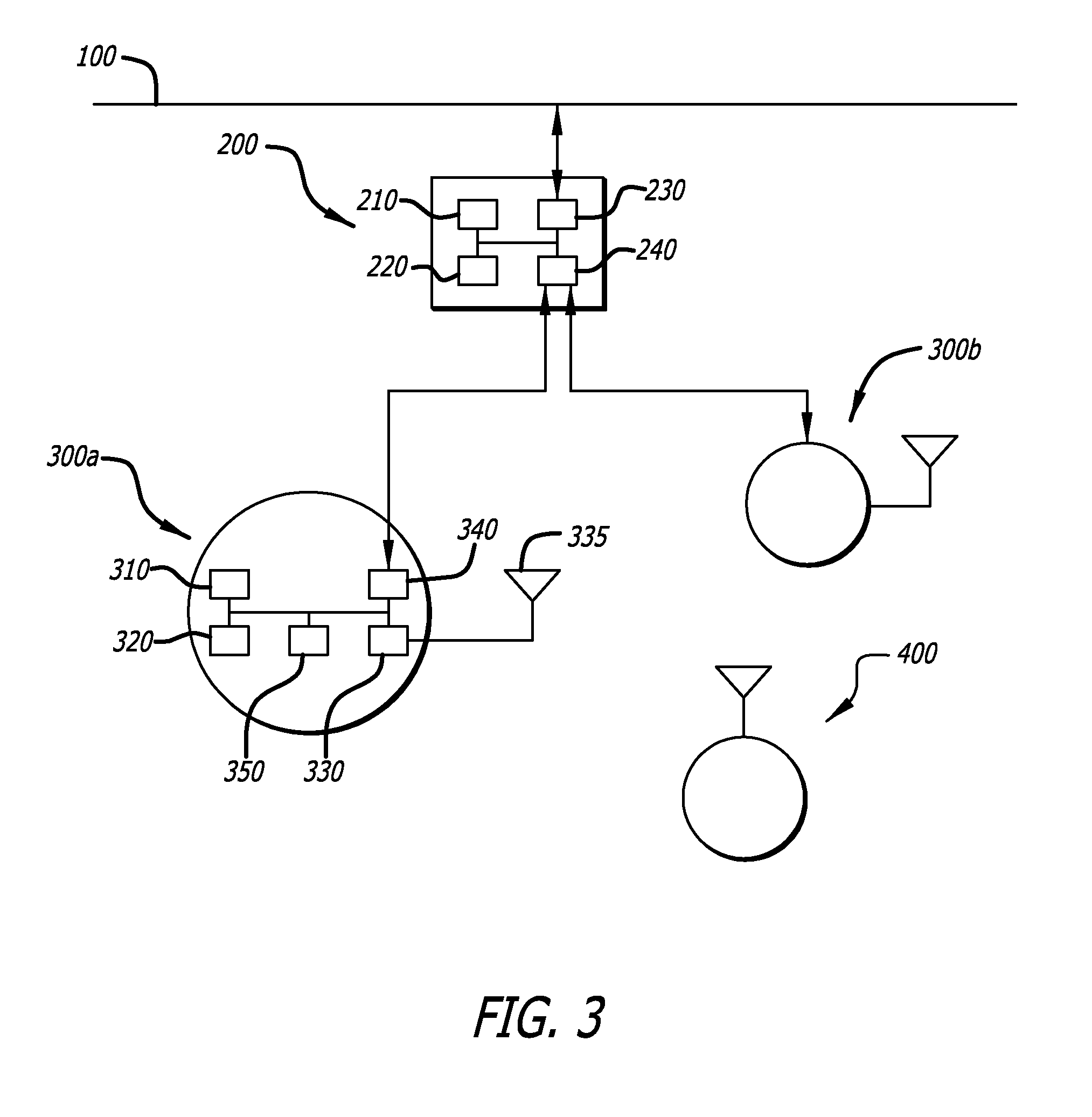
[0016]As shown in FIG. 3, a wireless network operating according to 802.11 standards supports connections of wireless clients 400 to a wired network. Wired network 100, such as a wired IEEE 802.3 Ethernet network, is connected to controller 200. Controller 200 supports connections 250 to access nodes 300a, 300b. These access nodes provide wireless communications to wireless client 400.

[0017]As is understood in the art, controller 200 is a purpose-built digital device having a CPU 210, memory hierarc...


PUM


Abstract

Sensing installed orientation of an antenna or access node in a wireless digital network. According to one aspect of the invention, an orientation sensor such as a 2 or 3 axis accelerometer is provided in the access node. The orientation sensor may be attached to the access node housing, directly or through a substrate, attached to the main logic board of the access node, or may be mounted to an antenna. The orientation sensor may be mounted to the same substrate as is used to form an antenna, or may be mounted on a separate substrate. When associated with an antenna, such as the orientation sensor on the same substrate as the antenna, or co-located with the antenna such as inside the same package, the orientation of the antenna may be sensed. Orientation data on the access node and / or antenna may be transmitted to the controller for the access node, and / or to clients of the access node. This orientation information may be used for example to verify or validate installation and positioning, for example comparing the actual orientation to the desired orientation as stored in a database. The orientation information may be used in modeling and / or displaying access node coverage. In access nodes with selectable antennas, the orientation information may be used to switch antennas.

Description

BACKGROUND OF THE INVENTION[0001]The present invention relates to wireless digital networks, and in particular, to the problem of sensing orientation of wireless access nodes and / or wireless antennas.[0002]Modern wireless digital networks typically consist of one or more access nodes connected to a controller, and typically provide services to wireless clients according to IEEE 802.11 standards. Particularly with access nodes featuring one or more built-in antennas, differences in mounting and orientation may have significant effects on coverage and signal strength. Additionally, when two access nodes are linked together, antenna orientation and polarization should be the same.[0003]Indoor access points, particularly those with integrated antennas, typically have two primary installation methods: wall mounted, or ceiling mounted. The differences in resulting antenna height and polarization between different mounting types and orientations may result in significant differences in cov...

Claims


Application Information

Patent Timeline
Patent Type & Authority Patents(United States)
IPC IPC(8): H03K9/00
CPCG01C9/00H04W24/00
Inventor VITEK, CLARK A.
Owner HEWLETT-PACKARD ENTERPRISE DEV LP
Why Eureka
Try Eureka