Wall gap fire block device, system and method

a fire block and wall gap technology, applied in the direction of walls, building components, construction, etc., can solve the problems of requiring a significant amount of time to install, the arrangement is not easy to meet the needs of construction, and the installation of conventional fire blocks is labor-intensiv

Active Publication Date: 2013-01-15
CEMCO LLC
View PDF28 Cites 73 Cited by
  • Summary
  • Abstract
  • Description
  • Claims
  • Application Information

AI Technical Summary

Benefits of technology

[0009]The fire block strip can be applied to a header track or other construction product, such as a bottom track, metal stud, metal flat strap or any other framing member that needs an open gap between the wallboard and a perimeter structure for movement (deflection or drift). The fire block strip allows the gap to stay open for movement and provides fire and smoke protection and sound reduction. Preferably, the fire block strip is applied such that it wraps the upper corner of the header track or other head-of-wall structure. The foam strip portion may be positioned on the top of the header track or other head-of-wall structure to provide a smoke, air and sound seal at the head-of-wall. The intumescent strip portion may be positioned on a side flange of the header track or side surface of the other head-of-wall structure such that the intumescent strip, portion is positioned between the header track or other head-of-wall structure and the wall board. The poly tape layer secures the foam strip portion and the intumescent strip portion to the header track or other head-of-wall structure and provides protection in the event that the wall is designed to accommodate vertical movement, which could result in the wall board rubbing against the fire block strip. However, the poly tape layer still permits the intumescent strip portion to expand when exposed to a sufficient temperature.

Problems solved by technology

Conventional head-of-wall fire blocks are typically labor-intensive to install.
As a result, most conventional fire blocks are expensive.
As noted, such an arrangement requires a significant amount of time to install.
In addition, over a period of time, the flexible coating may degrade, resulting in cracks and / or flaking.
As a result, it is possible that the fire resistant material may become dislodged from the head-of-wall gaps thereby reducing the effectiveness of the fire block.

Method used


Image

  • Wall gap fire block device, system and method
  • Wall gap fire block device, system and method
  • Wall gap fire block device, system and method

Examples


Embodiment Construction

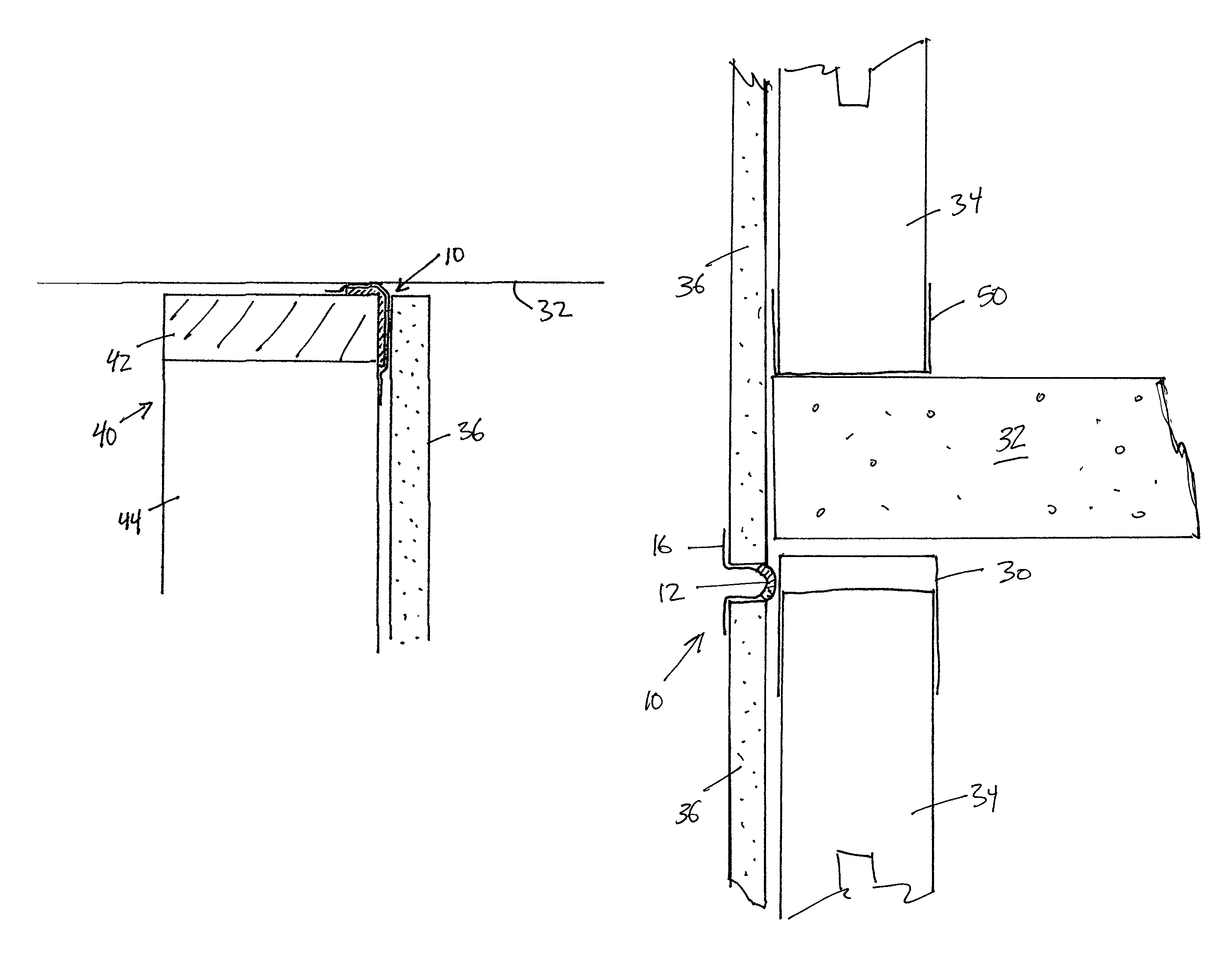
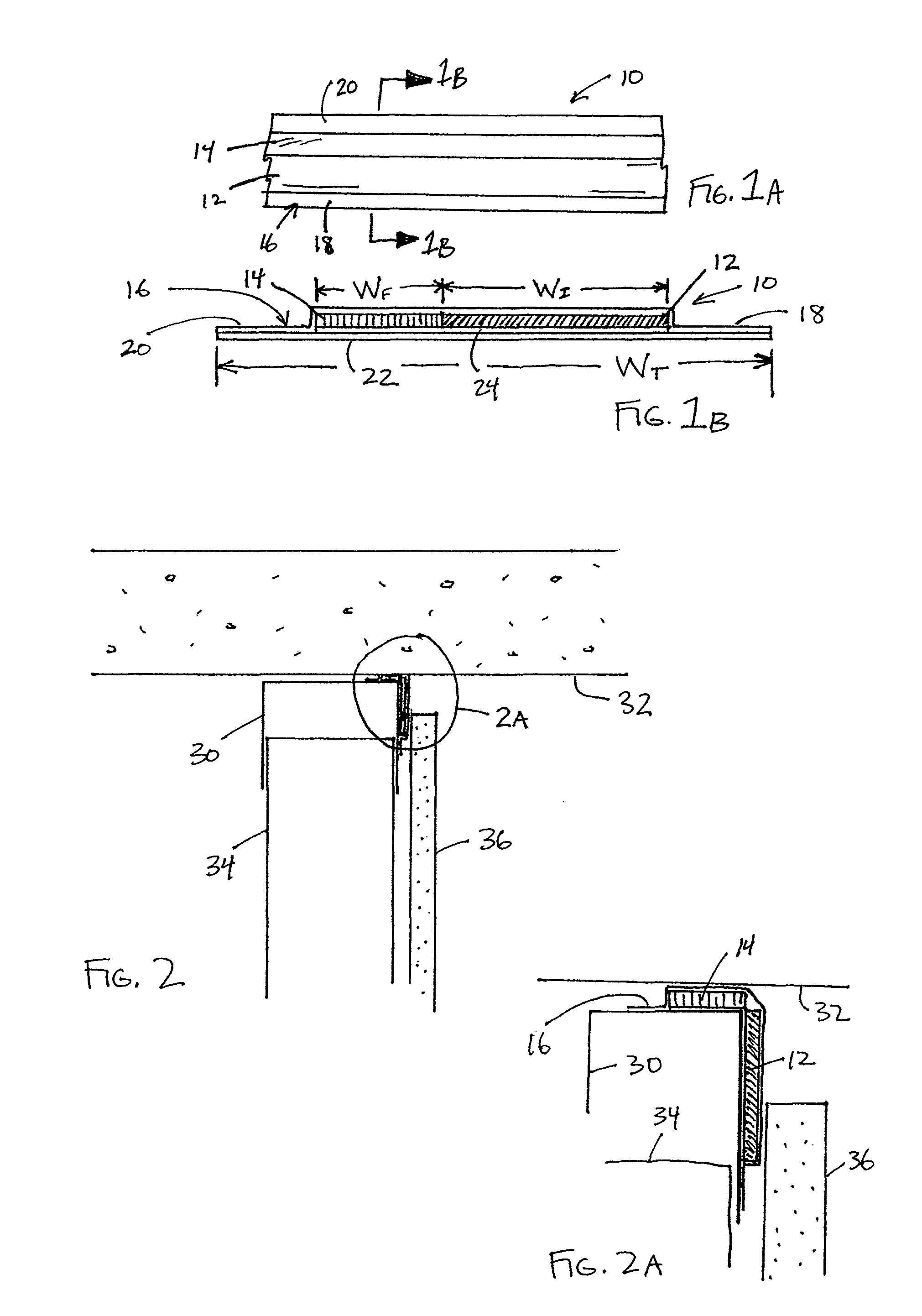
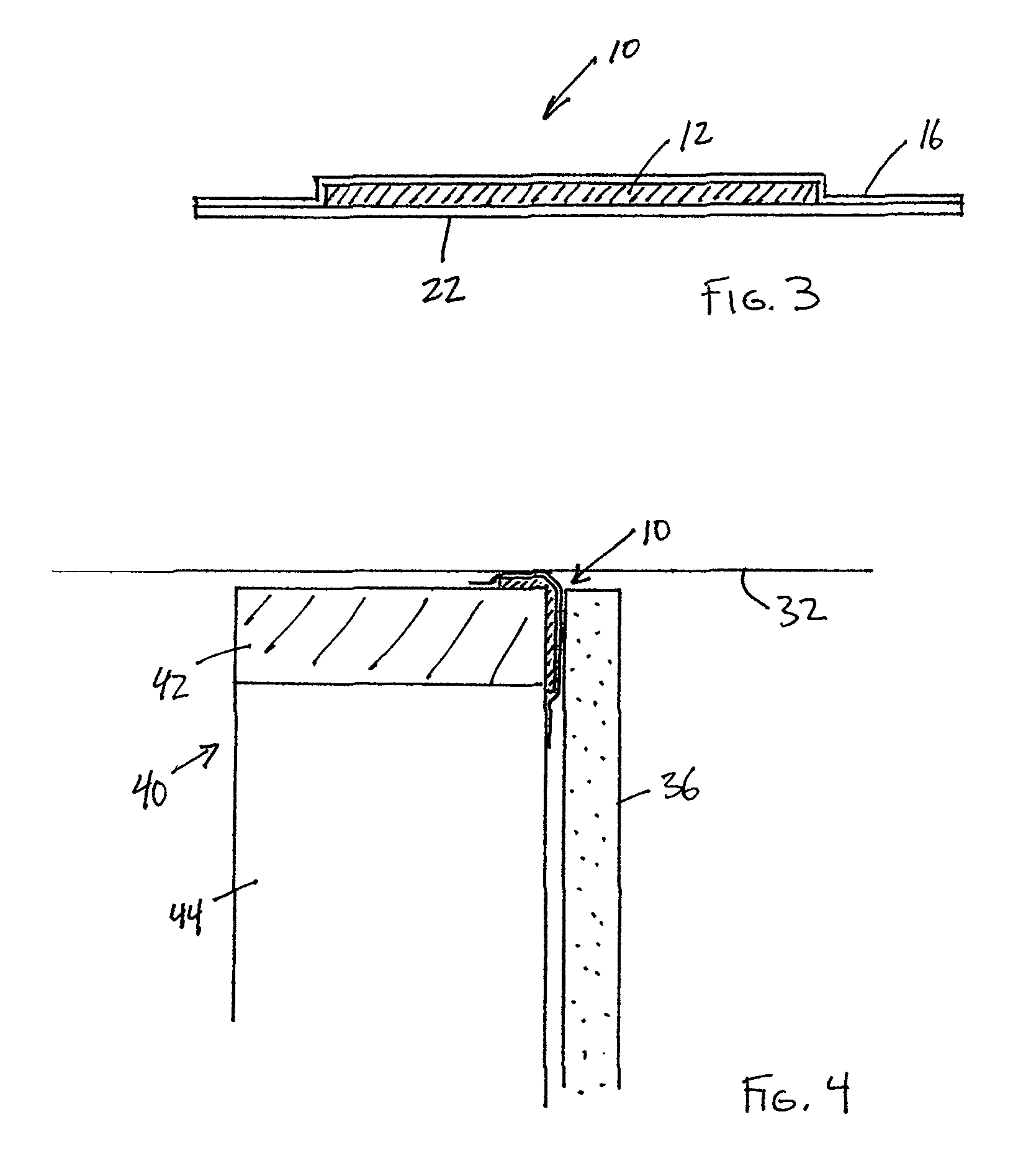
[0026]FIGS. 1a and 1b illustrate a fire block strip assembly 10, which is also referred to herein as a fire block strip or, simply, a strip. The fire block strip 10 is an elongate strip assembly that preferably is constructed as an integrated assembly of multiple components. The fire block strip 10 may be supplied on a roll, in a folded arrangement or any other suitable manner. Preferably, the fire block strip 10 is provided as a separate component that is applied to a head-of-wall in the field, as is described in greater detail below. Alternatively, the fire block strip 10 may be pre-assembled to a header track during manufacture.

[0027]The illustrated fire block strip 10 includes a fire-resistant material strip portion 12 (“fire-resistant material strip 12”) and a foam strip portion 14 (“foam strip 14”). The fire-resistant material strip 12 and the foam strip 14 are positioned side-by-side and co-planar with one another. A cover layer 16 covers both the fire-resistant material stri...


PUM


Abstract

Fire block devices for application to a wall component. The fire block device can be a strip that includes a fire-resistant material strip comprised of a material that expands in response to sufficient heat to create a fire-resistant barrier. An optional foam strip comprised of a foam material can be placed side-by-side with the fire-resistant material strip. A cover layer covers the fire-resistant material strip and the optional foam strip, if present. The cover layer includes opposing side portions positioned on opposing sides of the fire-resistant material strip and foam strip, if present. The cover layer is comprised of a tape having an adhesive on an underneath surface thereof such that adhesive on the side portions are capable of securing the fire block strip to a wall component. The fire block strip can be applied to a header track, footer track or wall stud, among other possible components.

Description

RELATED APPLICATIONS[0001]This application claims the benefit under 35 U.S.C. §119(e) to U.S. Provisional Patent Application No. 61 / 244,277, filed Sep. 21, 2009, which is incorporated in its entirety by reference herein.BACKGROUND OF THE INVENTION[0002]1. Field of the Invention[0003]The present invention relates to fire-resistant arrangements for building structures. In particular, disclosed arrangements are wall gap fire resistant structures or “fire blocks” that reduce or prevent fire, air, smoke and heat from passing from one side of a wall to the other side through a wall gap.[0004]2. Description of the Related Art[0005]Conventional head-of-wall fire blocks are typically labor-intensive to install. As a result, most conventional fire blocks are expensive. One example of a conventional fire block arrangement involves a fire resistant material, such as mineral wool, stuffed into gaps at the head-of-wall. Once the gaps are filled with the fire block material, a flexible coating, su...

Claims


Application Information

Patent Timeline
Patent Type & Authority Patents(United States)
IPC IPC(8): E04C2/00
CPCE04B1/948E04B2/7411E04B2/7457
Inventor PILZ, DON A.POLIQUIN, RAYMOND E.
Owner CEMCO LLC
Why Eureka
Try Eureka