
Cockpit rudder control mechanism for an aircraft

a control mechanism and cockpit technology, applied in the field of can solve the problems of affecting the construction of aircraft, difficult to remove, repair or replace typical cockpit rudder control mechanisms, and insufficient symmetric motion for users, and achieve the effect of more comfor

Active Publication Date: 2013-01-15
TEXTRON INNOVATIONS
View PDF27 Cites 14 Cited by
  • Summary
  • Abstract
  • Description
  • Claims
  • Application Information

AI Technical Summary

Benefits of technology

[0010]As the carriage is translated it moves the vertical members, linkages, rotational collar and rudder pedals simultaneously. This translation allows users of different heights to adjust the location of the rudder pedals to a position that is safe and comfortable. It also allows the carriage, vertical members, rudder pedals, linkages and rotational collar to be removed as a unit to provide for ease of installation and maintenance.
[0011]In embodiments, the operation of the cockpit rudder control mechanism also provides for an asymmetric response providing more comfort to the user thereof. When one rudder pedal is moved in the forward direction, the other pedal moves aft a distance that is shorter than the distance moved by the forward pedal.

Problems solved by technology

Later manufacturing steps must be performed around the mechanism, further impeding aircraft construction.
Also, typical cockpit rudder control mechanisms are difficult to remove, repair or replace after initial installation.
This symmetric motion is not optimal for a user.

Method used


Image

  • Cockpit rudder control mechanism for an aircraft
  • Cockpit rudder control mechanism for an aircraft
  • Cockpit rudder control mechanism for an aircraft

Examples


Embodiment Construction

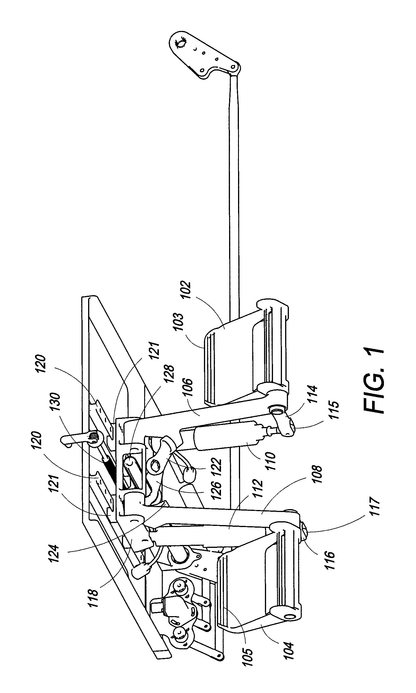
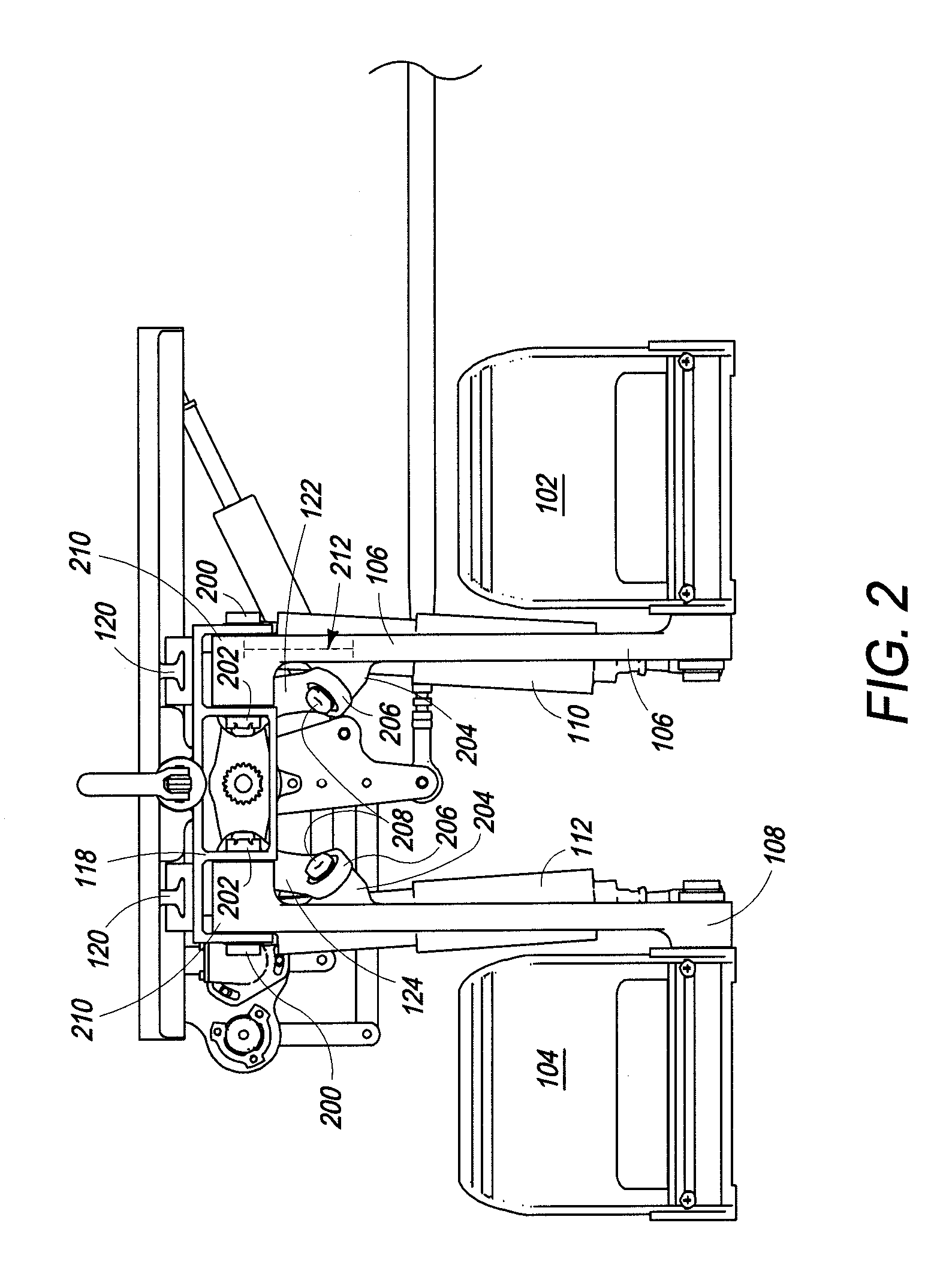
[0023]Referring now to FIG. 1, a perspective view of the cockpit rudder control mechanism 100 is shown. Rudder pedals 102 and 104 are pedals for use in receiving control input from the pilot of an airplane, specifically for receiving control input for the yaw axis of flight control. Rudder pedals 102 and 104 are pivotally attached to one end of vertical members 106 and 108, respectively. Rudder pedals 102 and 104 are also pivotally attached to one end of vertical members 110 and 112 by arms 114 and 116, respectively. Arms 114 and 116 are fixedly attached to rudder pedals 102 and 104, thus maintaining the angle between the rudder pedal 102 and 104 and the arm 114 or 116 attached to the pedal.

[0024]Vertical members 106, 108, 110 and 112 depend from and are pivotally attached at one end to adjustable carriage 118, and may also be referred to as depending members. The pivotal attachments between vertical members 106, 108, 110 and 112 and carriage 118 and rudder pedal 102 and 104 allow t...


PUM


Abstract

A cockpit rudder control mechanism is described for accepting aircraft control input utilizing rudder pedals depending from a movable carriage to rotate a shaft. The mechanism may be removed from the aircraft for maintenance and the position of the mechanism within the aircraft may be adjusted for a particular user. Movement of the rudder pedals is conveyed by linkages to a collar which rotates a shaft. The rotation of the shaft is measured for control input to the aircraft or is transferred to the mechanical control systems for the aircraft.

Description

BACKGROUND[0001]1. Field of the Invention[0002]The cockpit rudder control mechanism described herein relates to aircraft, specifically to aircraft control systems. More specifically it relates to systems for accepting control input from a pilot, co-pilot or other users of the cockpit rudder control mechanism. The cockpit rudder control mechanism also relates to adjustable and removable control system inputs.[0003]2. Description of the Related Art[0004]Because of the way they are integrated into the aircraft, typical cockpit rudder control mechanisms must be installed early in the manufacturing process. Later manufacturing steps must be performed around the mechanism, further impeding aircraft construction. Also, typical cockpit rudder control mechanisms are difficult to remove, repair or replace after initial installation.[0005]Typical cockpit rudder control mechanisms also have a symmetric response to user input. More specifically, when one rudder pedal is pushed a certain distance...

Claims


Application Information

Patent Timeline
Patent Type & Authority Patents(United States)
IPC IPC(8): B64C19/02
CPCB64C13/04B64C13/044
Inventor GARDNER, KENNETH D.
Owner TEXTRON INNOVATIONS
Learn More