Aid for lifting and carrying a mass/object

Inactive Publication Date: 2005-06-21
SM & JB ENTERPRISES
26 Cites 32 Cited by

AI-Extracted Technical Summary

Problems solved by technology

Although many devices have been designed and are currently in use to lift sedated, injured, or unconscious patients from the ground or other surface on which they are lying helplessly into a stationary chair, wheelchair, bed, cot or other patient transport device, operating table, etc., these known devices are bulky, heavy, and awkward to handle in-and-of themselves, and difficult if not possible to utilize in confined spaces (such as a damaged vehicle, behind furniture, in a ...

Benefits of technology

[0010]It is a primary object of this invention to provide an aid for lifting and carrying a mass such as a mammal or object, that includes a flexible device with a plurality of tiered handles, or hand-holds, along an underside of each of a first and second extension of a flexible elongated support member. Adjustable-length first and second strap portions of a strap/belt member (fabricated as one unitary or multiple integral, or separated, sec...

Abstract

A device (10) having a flexible elongated support member (11) having an upperside, an underside, and a first and second extension (16, 18) on either side of a central-portion, each of the first and second extensions have a free-end. A first and second strap portion (26, 27) affixed to and extending from the upperside between the free-ends of the support member (11). These strap portions are employed for positioning around the mass (20). A matable first and second coupling (28A, 28B) is attached to a free end-section of each of the first and second strap portions. The strap portions (26, 27) may be adjustable in length with each respective coupling being slidably attached to its respective free end-section. Extending from the underside of the support member and along each of the first and second extensions, is a respective first and second plurality of handles (12A, 12B, 12C, 14A, 14B, 14C) affixed to at least the underside. Also, a method of lifting to carry a mass (20) employing a device (10) comprising a flexible elongated support member (11) characterized herein. The method includes: placing the support member (11) under the mass (20) and positioning the first and second strap portion (26, 27) therearound; engaging a first and second coupling (28A, 28B) such that the mass fits snug within the strap portions; and grasping and applying a force to at least one handle from each of a first and second plurality of handles extending from, and affixed to, the underside along a respective one of the first and second extensions, to aid in the lifting.

Application Domain

Travelling carriersHolders +9

Technology Topic

Coupling

Image

  • Aid for lifting and carrying a mass/object
  • Aid for lifting and carrying a mass/object
  • Aid for lifting and carrying a mass/object

Examples

  • Experimental program(1)

Example

[0036]Exhibit A is a copy of several photos illustrating a device (e.g., that at 10) of the invention employed as an aid to lift and carry, to reposition, a mass such as the patient shown as being lifted from a position lying on the floor to a position sitting in a chair.
DETAILED DESCRIPTION OF PREFERRED AND ALTERNATIVE EMBODIMENTS
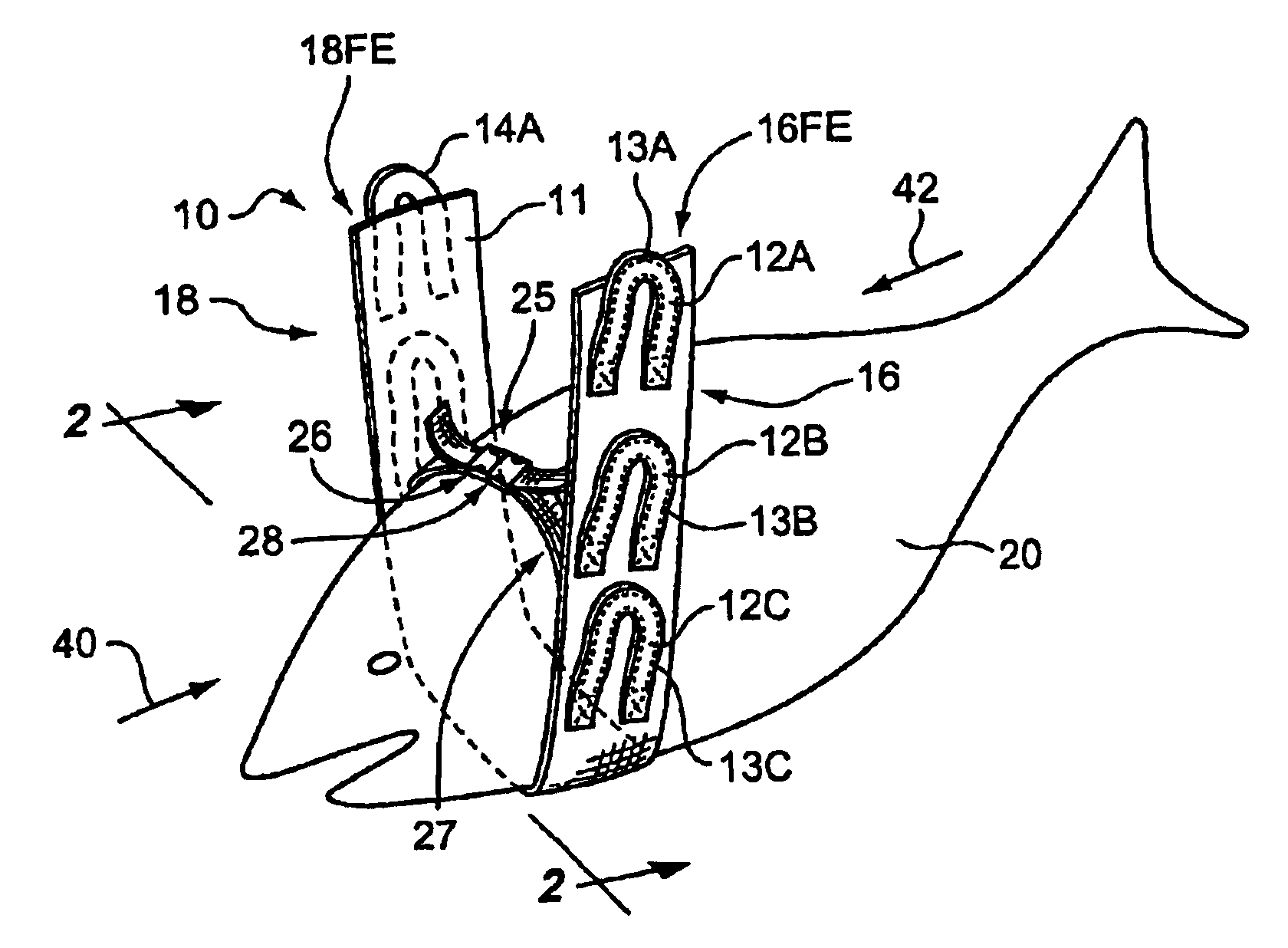
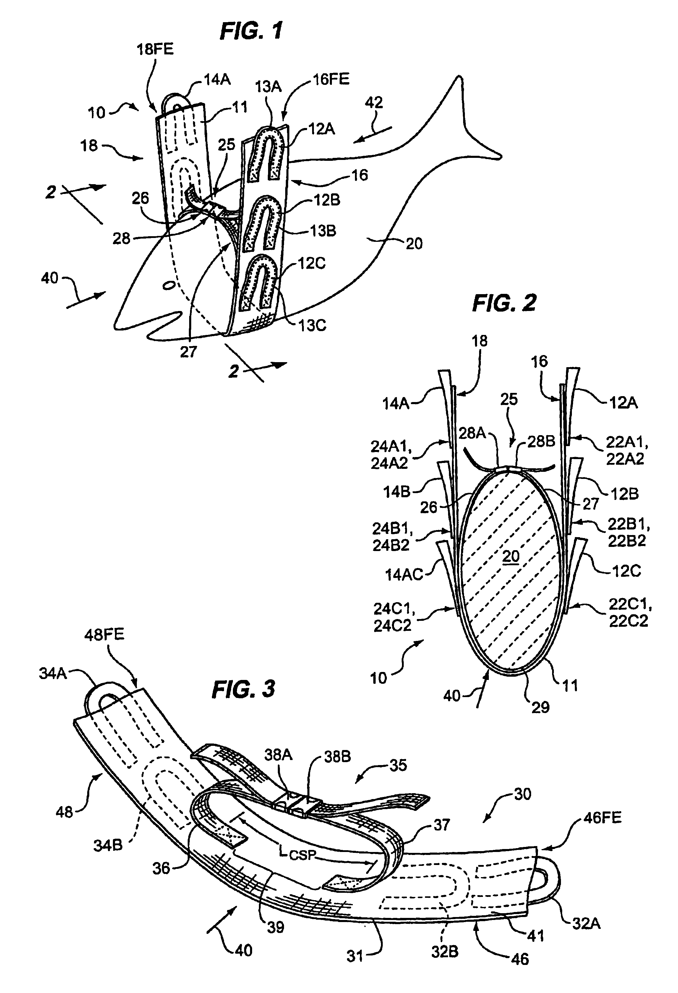
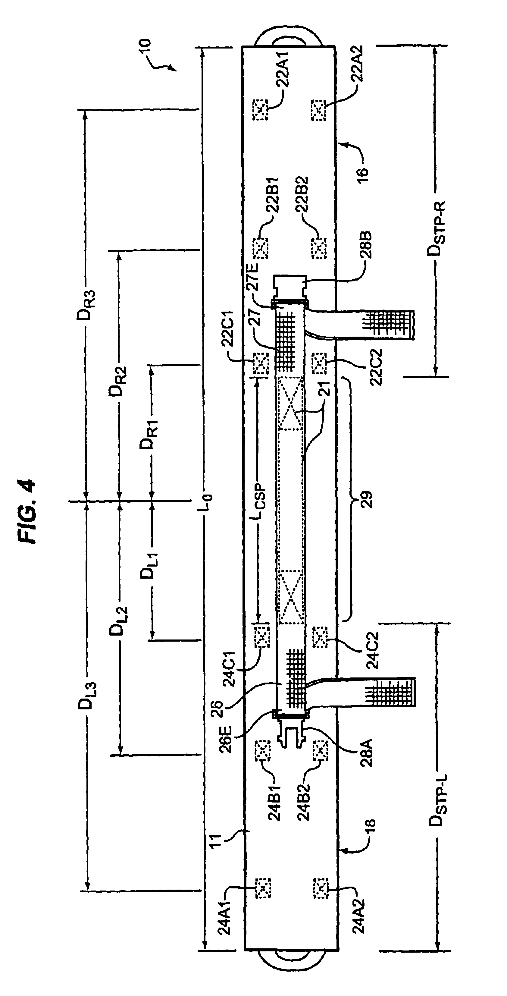
[0037]The device 10 of the invention in FIG. 1 is employed around a mass such as the identifiable fish-shape, outlined for reference only, at 20. One can appreciate the very many types of masses (from mammals to inanimate objects) on which device 10 can be used to aid in lifting and carrying. Mass 20 may be placed atop elongated support member 11, or the mass lifted and support member 11 placed under mass 20, from either of the directions labeled 40 and 42. Elongated support member 11 (see, also, details depicted in FIGS. 4 and 5) has two extensions identified and labeled 16, 18 on either side of a central-portion identified and labeled 15. At each end of extensions 16, 18 a respective free-end has been identified and labeled 16FE and 18FE for purposes of describing the features of device 10. Along extension 16, in a three-tiered hand-hold fashion, are handles 12A, 12B, 12C and along extension 18 one can see the top of handle 14A and another handle (not labeled, in phantom). Interposed within each handle at 12A, 12B, 12C is a length of cord 13A, 13B, 13C; in such a case, handles 12A, 12B, 12C, 14A, etc. can be fabricated from lengths of flexible tube stock (such as tubular webbing) and affixed, by way of suitable stitching with sturdy threading for example, to the support member. The adjustable strap/belt member 25 consists, as shown in FIG. 1, of two strap portions 26, 27 and coupling pair 28 engaged to join strap portions 26, 27. Strap portions 26, 27 can then, if desired or needed, be adjusted to create a snug fit around mass 20, thus, temporarily suitably anchoring mass 20 so it can be lifted and carried/repositioned.
[0038]In FIG. 2, one can better appreciate the flexibility in design utilizing a multi-tier structure of hand-holds, here, shown as two three-tier sets labeled 12A-12C and 14A-14C, each set located along the underside as attached to a respective extension 16, 18 of the support member 11. As can be viewed more-easily in the plan views of FIGS. 4-5, each handle 12A, 12B, 12C has a respective pair of ends 22A1-22A2, 22B1-22B2, 22C1-22C2 permanently located as shown affixed to the underside along extension 16 (the right hand side of FIG. 2). Likewise, each handle 14A, 14B, 14C has a respective pair of ends 24A1-24A2, 24B1-24B2, 24C1-24C2 permanently located as shown affixed to the underside along extension 18 (the left-hand side of FIG. 2). Adjustable strap/belt 25 has a quick-release coupling pair 28A, 28B (for example, preferably, a releasable mechanism such as a buckle, quick-release clip, VELCRO® hooks-and-loops, traditional seatbelt buckle, backpack/fanny-pack buckles, spring-release or other type of suitable releasable fastener capable of being attached to a strap member) and is shown wrapped around mass (e.g., a mammal body) to temporarily anchor it to support member 11 while mass 20 is being lifted, moved, and positioned/repositioned.
[0039]Each end of the strap/belt 25 is preferably affixed or secured by suitable means for permanent location (stitching, adhesive, thermo-forming/heat-bonding, preforming integral with the member 11, and so on) to extend from support member 11 such that an object/mass 20 positioned along the direction of arrow 40, for example, contacts strap portions 26, 27, 29 of belt/strap 25 as well as (since the belt/strap 25 has a width smaller than support member 11) the upperside of support member 11. Preferably, the belt/strap 25 can be tightened around mass 20 using couplings 28A, 28B that are slidably attached to respective free end-sections of this strap/belt 25.
[0040]FIG. 3 further illustrates the flexibility of design of the invention. The device 30 has two-tiered hand-holds: Two sets of handles are shown, one set labeled 32A-32B located along extension 46 (having a free-end identified as 46FE) and another set of handles 34A-34B located along extension 48 (having a free-end identified as 48FE). The adjustable strap/belt labeled 35, by way of further example, is shown with two strap portions 36, 37 attached to the upperside of support member 41 with a spacing 39 therebetween. Quick-release buckles labeled 38A, 38B join strap portions 36, 37. For purposes of discussion, a distance between the areas from which strap portions 36 and 37 extend from the upperside is identified and labeled LCSP.
[0041]The plan views of upperside of support member 11 shown in FIG. 4 and the underside of support member 11 in FIG. 5 provide reference details to additional novel structure of the invention. Here, the support member overall length is designated as L0. For example, the tiered handle layout along the underside may be as follows: the ends 24C1, 24C2 of a first handle (14C) of the first plurality are each located a distance dl1 as referenced from a central-area of the central-portion identified in FIG. 5 at 15, the ends 22C1, 22C2 of a first handle (12C) of the second plurality are each located a distance dr1 as referenced from the central-area, the ends 24B11, 24B2 of a second handle (14B) of the first plurality are each located a distance dl2 as referenced from the central-area, the ends 22B1, 22B2 of a second handle (12B) of the second plurality are each located a distance dr2 as referenced from the central-area, the ends 24A1, 24A2 of a third handle (14A) of the first plurality are each located a distance dl3 as referenced from the central-area, and the ends 22A1, 22A2 of a third handle (12A) of the second plurality are each located a distance dr3 as referenced from the central-area. In this configuration as referenced, one can appreciate that distances dl1≈dr1, dl2≈dr2, dl3≈dr3, distance dl2 is preferably greater than dl1 and distance dl3 is preferably greater than dl2. Also, where elongated support member has an overall length defined as L0, one may choose to place the first handles 14C, 12C such that the difference of the two quantities, L0/2−dl1, is greater than or equal to approximately a value of one-sixth to one-fifth the overall length of the support member, or L0/6 to L0/5.
[0042]Turning to FIG. 4, strap portions 26, 27 each have a coupling 28A, 28B slidably attached to a respective free end-section 26E, 27E. Strap portions 26, 27 may be integral with a center strap portion 29 having a length, LCSP, for reference. A periphery of the center strap portion 29, here, is shown affixed by way of a plurality of stitches 21 (with or without an additional fastening mechanism, such as an adhesive) through at least the upperside of support member 11. Alternatively, the strap portions may be affixed to the upperside in spaced relationship (see, once again, FIG. 3), a spacing 39 therebetween being generally less than or equal to central-portion 15. Referring to both FIGS. 4 and 5, (support member referenced length, L0): each strap portion 26, 27 can be affixed so that it extends from a respective first and second area of the upperside located a distance (respectively DSTP-L, DSTP-R) at least equal to, for example, a value of one-sixth to one-fifth the overall length of the support member, or L0/6 to L0/5, from the free-end 18FE, 16FE of the respective extension 18, 16. The central-portion of the support member may be fabricated to include a pocket (closed at one end as shown in phantom 71) or a sleeve-pocket (open at both ends) adapted for receipt in the direction 78 of an end of stabilizing panel 70 (with or without hand-hold apertures such as those labeled 74, 72).
[0043]As illustrated in FIG. 6 (see also FIG. 8), to accommodate lifting and carrying of larger-sized masses, an extender-strap 65 includes a belt/strap member 61 having a free end-section 68E to which coupling 68A is slidably attached and another free end-section 66E to which coupling 68B is slidably attached. The device of the invention in FIG. 8 at 130, shows coupling 68A of extender-strap 65 in releasable-engagement with coupling 138A of strap portion 136 and coupling 68B in releasable-engagement with coupling 138B of strap portion 137. A relatively-rigid structure can be employed, such as the contoured board at 170 adapted for supporting the mass 120 (such as the roll of fencing, or carpet, illustrated in FIG. 8). Such a structure preferably has a left and right aperture (174, 172—which may be hand-holds of a spine board, such as is currently in use) through which a respective strap portion 136, 137 has been threaded.
[0044]One can readily appreciate the advantages of the technique of the invention by way of FIG. 7 as well as attached Exhibit A, incorporated herein by reference. Here, operation of a device of the invention (such as that at 10 in other figures) in connection with a human initially lying on the ground/floor is depicted. As illustrated in FIG. 7, once the support member has been place under the mass (100) and the strap portions positioned around the mass, the couplings 28A, 28B are engaged such that the mass fits snug within the strap portions as shown. Next, a user 80 grasps handles (including hand-hold 14A) extending from the left hand extension of device 10 and user 90 grasps two handles (hand-holds 12A and 12B in one hand) as well as an unlabeled third hand-hold extending from the right hand extension of device 10. An upwardly force can be applied by the users 80, 90 to lift the mass (patient 100) for repositioning.
[0045]Exhibit A is a copy of several photo snapshots depicting the technique of the invention, whereby a device, such as that at 10 in FIGS. 1, 2, 4, 5, is in use to lift a human, by way of example only, from an original position lying on the floor to a sitting position. See also, FIG. 7. For further reference, for further detail of unique features of the invention refer to FIGS. 4-5 where device 10 is illustrated in a flat-open, unengaged position (upperside and underside plan views, respectively). The device can be operated by two people according to the following in any type of situation, by way of example only reference below is made to a ‘patient’ or person—but, the device can lift objects, too:
[0046](A) Position the destination chair, wheelchair, dolly, stair chair, bed or cot near the patient/person/mammal.
[0047](B) Unroll lifter and release 2-inch side-release buckle. Place device flat on the floor centered above patient's head with the tiered-handle side (underside) down.
[0048](C) A rescuer on each side of the patient grasps the arms (the inside of patient's nearest elbow) and lift the shoulders just enough to slide the device under the patient's back, aligned with the patient's armpits.
[0049](D) The extensions of the device are lifted/positioned (by way of sliding under the patient's arms/armpits) alongside and under the patient's chest-area.
[0050](E) If the extender-strap is not needed for a larger-sized patient, join/connect the ends of the side-release buckles together and adjust the length of the two-inch webbing by pulling from the ends until snug on the patient's chest (e.g., until belt/strap is taut with little ‘play’). If the patient is too large, connect the extender-strap to each buckle of the strap portions and adjust any of the extender-strap, and/or either strap portion extending from the support member.
[0051](F) Each rescuer should select the handle appropriate to his or her height and lift using the leg muscles as much as possible.
[0052](G) Pivot patient onto an interim or final destination/item (chair, wheelchair, or cot, or help patient to a standing position, pivot onto a bed, recliner, or other destination) alternatively, a third person can be engaged to roll the destination item under the patient.
[0053](H) Remove the device only after the patient is securely into a chair, wheelchair, bed, or transport device.
[0054]A wide variety of flexible, pliable materials of suitable strength may be used for the elongated support member (such as those ast 11, 41), belt/strap portions, the extender-strap, and the handles (especially where a flexible tubing is used) including fabrics, webbing, and cording/cord. Using a flexible material allows for strap portions to be affixed with a plurality of stitches through at least the upperside and each handle to be affixed with a plurality of stitches through at least the underside. “Fabric” as used throughout, includes any flexible material made of an individual component or combination, or layers, of cloth, canvas (heavy, course, closely-woven fabric of, usually, natural fibers such as cotton, hemp, or flax), fibers (synthetic or natural), polymeric or other synthetic film, sheeting, or foam—whether laminated or coated—including duck-fabric; “webbing” as used throughout, includes any strong closely woven fabric or cording used for example, in seatbelts, upholstery, harnesses, climbing/hiking or packing equipment, garments, etc.; flat, rolled, or solid rope-like “cord”/“cording” as used throughout includes any twisted strands of fiber, braided strands of string/rope, a fabric/cloth with ribs. Coupling as used throughout include any device that serves to connect the ends of adjacent parts/pieces. By way of example, only, for reference a device of the invention such as that at 10 illustrated in FIGS. 4-5 (upperside and underside plan views, respectively) can be fabricated with the following components:
[0055](A) 861 7500# N 6″—six-inch nylon webbing manufactured by the Murdock Webbing Co. Inc. of Tarboro, N.C. 27886-1197. Minimum tensile strength of 45,000 lbs.
[0056](B) N0075-2″7K100—two-inch nylon webbing manufactured by TapeCraft Corp., Anniston, Ala. 36202. Break strength rated at 4.000 lbs.
[0057](C) LB50RD—two-inch, double-adjustment side-release buckles, manufactured by YKK (USA), Inc., Santa Fe Spring, Calif. 90670. Not yet strength rated, however 1″ buckle of same design rated at 300 lbs.
[0058](D) N0026-1″ nylon tube webbing manufactured by TapeCraft Corp., Anniston, Ala. 36202. Break strength rated at 3,000 lbs.
[0059](E) ⅝—inch diameter braided polyester rope, any manufacturer; and
[0060](F) UV—resistant nylon yarn thread, any manufacturer.
[0061]Two-inch nylon webbing is attached to the six-inch nylon webbing using a straight stitch on a perimeter sewing pattern. The one-inch nylon tube webbing is attached to the six-inch nylon webbing using a box X sewing pattern. A length of ⅝-inch braided polyester rope is inserted into each handle prior to attachment to make the handles more comfortable. One end of a side-release buckle is threaded onto each extending end of the two-inch webbing using a non-slip threading pattern.
[0062]While certain representative embodiments and details have been shown merely for the purpose of illustrating the invention, those skilled in the art will readily appreciate that various modifications may be made to the embodiments represented without departing from the novel teachings or scope of this invention. Accordingly, all such modifications are intended to be included within the scope of this invention as defined in the claims. Although the commonly employed preamble phrase “comprising the steps of” may be used herein, or hereafter, in a method claim, the applicants in no way intend to invoke 35 U.S.C. Section 112 ¶6. Furthermore, in any claim that is filed herewith (as well as any claim added or amended), any means-plus-function clauses used, or later found to be present, are intended to cover the structures described herein as performing the recited function and not only structural equivalents but also equivalent structures.
[0063]The plan view of the underside of support member 211 of the alternative device labeled 210 in FIG. 9A, illustrates the placement of a support-loop affixed/connected to device 210 among the tiered handles along each of its extensions 16 and 18 (see FIG. 5). As can be viewed in connection with FIGS. 10A-10B, each of the support-loop pairs labeled 274, 272 and 276, 278 are shaped to accept a belt/strap member (such as that labeled 61 in FIG. 6), for use to further assist in supporting a mass such as the human figure labeled 220 in FIGS. 10A and 10B. By way of illustrative example, the alternative support-loop mechanisms are shown along each extension 16 and 18 in FIG. 9A so that support-loops 274 and 276 are connected among the hand-holds 214A-214C secured along the left-hand extension; and support-loops 272 and 278 are connected among the handholds 212A-212C secured along the right-hand extension. The plan view of the upperside of device 310 in FIG. 11A, illustrates yet another alternative placement for a support-loop pair, here labeled 372 and 374, along support member 211. The support-loops operate in pairs as can be appreciated by turning also to FIGS. 10A-10B and FIG. 11B: only one support-loop need be employed along each extension to accept belt 61. In operation, as seen in FIGS. 10A-10B and 11B, belt 61 is employed as a torso/back support.
[0064]Shown in FIG. 9A, prior to being permanently located along a respective extension of member 211, each hand-hold 214B, 212B is looped through a respective loop 277L or 279L of support-loop mechanisms 276, 278. A second looped-portion labeled 277S, 279S of support-loops 276, 278, is oriented to accept belt 61 in the manner depicted in FIG. 10B. For detail concerning support-loop mechanisms 276, 278 see the side view of mechanism 278 in FIG. 9B. Also shown in FIG. 9A are support-loop mechanisms 274, 272 affixed to member 211 at 275A, 275B and 273A, 273B respectively, by stitching and/or an adhesive, or other suitable fastening means similar to that used to affix each hand-hold/handle (e.g., 12A is affixed at 22A1, 22A2 in FIG. 5) to member 11. Support-loop straps 274, 272 are oriented so that each can accept belt 61 to support a mass 220 as depicted in FIG. 10A (a view of the back of patient 220). Here, mid-tier handles 214B, 212B are shown in phantom for simplification. Labeled for reference in phantom at 221 (FIG. 9A) is stitching employed to affix the center strap portion 29 (see FIG. 4) to member 211. Alternatively, the support-loop pair shown in phantom in FIG. 11B at 372, 374 are affixed to the upperside of support member 211 allowing belt 61 to fit snug around the torso and under the arms. Once again, it can be appreciated that support-loop mechanisms 272, 274; 276, 278; and 372, 374 are employed in pairs as illustrated in FIGS. 10A, 10B and 11B respectively to support a mass being lifted by a device of the invention.
[0065]In each of FIGS. 10A-10B and FIG. 11B, strap portions 26 and 27 of belt/strap 25 are shown coupled together over the lap of a patient (mass) 220, by way of example, similar to the way a lap seat belt operates in a vehicle. Devices 210 and 310 operate in a manner similar to that illustrated in FIG. 7: once the support member 211 has been placed under a mass 220 and strap portions 26, 27 are positioned and coupled around the mass in a snug fit, a belt 61 may be placed and coupled around the middle of the patient as shown in FIGS. 10A-10B and FIG. 11B to lend back support. At least two users (such as the individuals identified at 80 and 90 in FIG. 7) each grasp handles extending from a respective side of device 210 or 310; then lift from the handles to aid in moving mass 220.

PUM

no PUM

Description & Claims & Application Information

We can also present the details of the Description, Claims and Application information to help users get a comprehensive understanding of the technical details of the patent, such as background art, summary of invention, brief description of drawings, description of embodiments, and other original content. On the other hand, users can also determine the specific scope of protection of the technology through the list of claims; as well as understand the changes in the life cycle of the technology with the presentation of the patent timeline. Login to view more.
Why Eureka
Try Eureka