
Methods of controlling fin height of FinFET devices by performing a directional deposition process

a technology of directional deposition and semiconductor devices, which is applied in the direction of semiconductor devices, basic electric elements, electrical equipment, etc., can solve the problems of reducing the channel length of a fet, reducing the distance between the source region and the drain region, and affecting the electrical potential of the source region and the channel. , to achieve the effect of efficiently inhibiting the electrical potential of the source region and the channel, the effect of reducing the length of the channel

Inactive Publication Date: 2013-01-15
GLOBALFOUNDRIES INC
View PDF18 Cites 35 Cited by
  • Summary
  • Abstract
  • Description
  • Claims
  • Application Information

AI Technical Summary

Benefits of technology

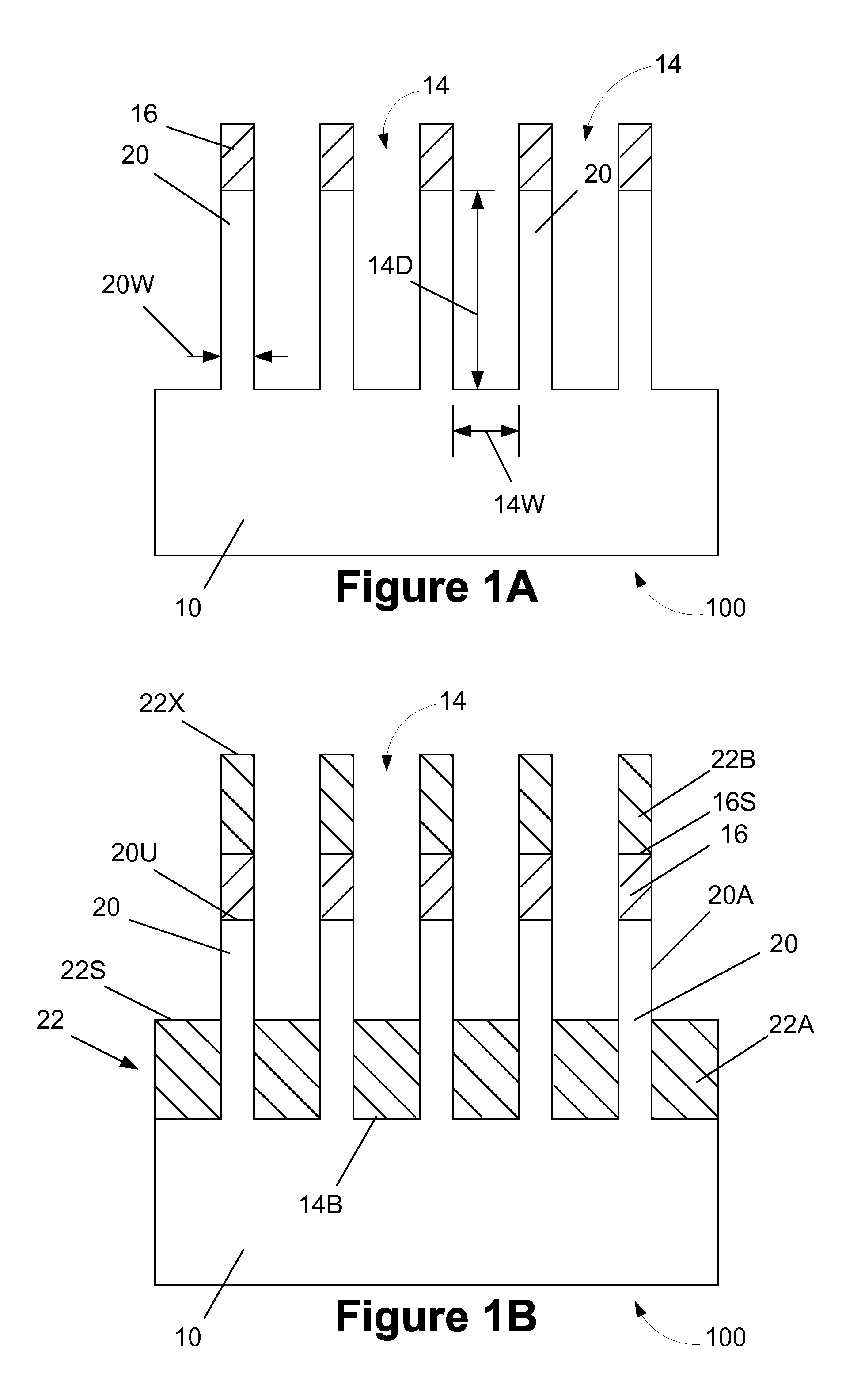
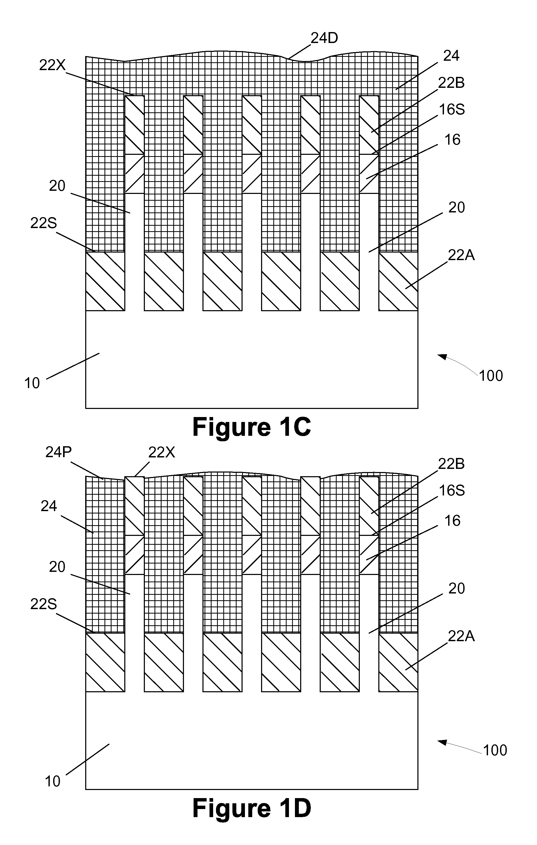
This patent describes methods for controlling the height of fins in FinFET devices. The methods involve depositing a material into trenches in a semiconducting substrate to form a fin structure, and then adding a layer of another material to overfill the trenches. The excess material is then removed to expose the surface of the first insulating material. These methods help to control the height of fins in FinFET devices and improve their performance.

Problems solved by technology

However, decreasing the channel length of a FET also decreases the distance between the source region and the drain region.
In some cases, this decrease in the separation between the source and the drain makes it difficult to efficiently inhibit the electrical potential of the source region and the channel from being adversely affected by the electrical potential of the drain.
Unfortunately, the CMP / etch-back process may not produce fins having a substantially uniform height for a variety of reasons.
More specifically, process variations in the CMP process and / or the etch-back process may produce fins that have unacceptable variations in fin height.
For example, the CMP process may not produce a truly planar surface on the layer of insulating material, i.e., there may be relatively large topography differences across the surface of the polished layer of insulating material.
Thus, even if the etch-back process is performed uniformly across the polished insulating material, the undesirable topography differences may simply be transferred to the remaining portions of the insulating material that are positioned in the bottom of the trenches after the etch-back process is completed.
Additionally, the etch-back process may not be uniform across the polished layer of insulating material.
As a result, there may be differences in thickness of the insulating material that is positioned in the bottom of the trenches.
As a result, the performance of FinFET devices made by employing the previously described CMP / etch-back process to establish the height of the fins in such a FinFET device may be less than desired or less than may be achieved if the fins in such a device had a substantially uniform fin height.

Method used


Image

  • Methods of controlling fin height of FinFET devices by performing a directional deposition process
  • Methods of controlling fin height of FinFET devices by performing a directional deposition process
  • Methods of controlling fin height of FinFET devices by performing a directional deposition process

Examples


Embodiment Construction

[0019]Various illustrative embodiments of the invention are described below. In the interest of clarity, not all features of an actual implementation are described in this specification. It will of course be appreciated that in the development of any such actual embodiment, numerous implementation-specific decisions must be made to achieve the developers' specific goals, such as compliance with system-related and business-related constraints, which will vary from one implementation to another. Moreover, it will be appreciated that such a development effort might be complex and time-consuming, but would nevertheless be a routine undertaking for those of ordinary skill in the art having the benefit of this disclosure.

[0020]The present subject matter will now be described with reference to the attached figures. Various structures, systems and devices are schematically depicted in the drawings for purposes of explanation only and so as to not obscure the present disclosure with details ...


PUM


Abstract

One illustrative method disclosed herein includes a forming plurality of trenches in a substrate to thereby define a fin structure for a FinFET device, forming a first region of a first insulating material within each of the trenches, wherein the as-deposited surface of the first insulating material is positioned below an upper surface of the fin, forming a layer of a second material that contacts the as-deposited surface of the first region of the first insulating material and overfills the trenches, performing at least one process operation to remove at least a portion of the layer of the second material from above the fin structure, and, after performing the at least one process operation, performing a second process operation to selectively remove the second material from above the first region of the first insulating material and thereby expose the as-deposited surface of the first region of the first insulating material.

Description

BACKGROUND OF THE INVENTION[0001]1. Field of the Invention[0002]Generally, the present disclosure relates to the manufacturing of sophisticated semiconductor devices, and, more specifically, to various methods of controlling the height of fins in FinFET semiconductor devices by performing a directional deposition process.[0003]2. Description of the Related Art[0004]The fabrication of advanced integrated circuits, such as CPU's, storage devices, ASIC's (application specific integrated circuits) and the like, requires the formation of a large number of circuit elements in a given chip area according to a specified circuit layout, wherein so-called metal oxide field effect transistors (MOSFETs or FETs) represent one important type of circuit element that substantially determines performance of the integrated circuits. A FET is a planar device that typically includes a source region, a drain region, a channel region that is positioned between the source region and the drain region, and ...

Claims


Application Information

Patent Timeline
Patent Type & Authority Patents(United States)
IPC IPC(8): H01L21/00
CPCH01L29/66795
Inventor XIE, RUILONGMILLER, ROBERT
Owner GLOBALFOUNDRIES INC
Learn More