Infrared motion sensor

a motion sensor and infrared technology, applied in the field of infrared motion sensors, can solve the problems of detectors emitted, false motion sensing, and limits on the monitored-volume design, and achieve the effect of reducing the cost of lens-based ir sensors and reducing the generated signal

Active Publication Date: 2013-01-15
SUREN SYST
View PDF4 Cites 18 Cited by
  • Summary
  • Abstract
  • Description
  • Claims
  • Application Information

AI Technical Summary

Benefits of technology

[0019]In one embodiment, each optical element in a respective array is at a different angular orientation relative to the respective detector element from the other optical elements so that the fields of view are oriented in different angular directions. The partition separating the first and second arrays of optical elements allows separation between the fields of view or monitored volumes of the two detector elements, so that the fields of view can be oriented individually for each detector element. This is different from prior art PIR sensor designs where fields of view have to be developed in opposite polarity pairs, and the fields of view for corresponding optical elements of the two detector elements must be oriented as a set. This embodiment has the advantage that all optical elements such as lenses or the like can have the same focal length, because net angular coverage is determined by field of view direction rather than varying focal lengths. Instead of varying focal length, orientation of each lens or optical element is varied individually in order to produce a more uniform “curtain” of monitored volumes or fields of view. This means that the front surface of the sensor can be made more even and attractive, while still taking advantage of the lower cost of lens-based IR sensors.
[0020]This embodiment of the invention allows realization of a long, narrow curtain shape without a lens-appearance problem, by using variable optical-element / detector-element juxtaposition rather than varying focal length to define the sub-volumes' or monitored volumes' effective angles. In contrast to prior art arrangements with optical elements of varying focal length, the embodiment described above has optical elements having fields of view of substantially equal angular width but oriented in different angular directions when viewed in a horizontal plane.
[0021]Since the thin wall or partition between the detector elements is transparent to visible / NIR light, such superfluous radiation still tends to fall equally on each of the opposed-polarity detector elements, so that signals from the opposite polarity detector elements resulting from such radiation cancel out. This greatly reduces the signal generated by superfluous radiation.

Problems solved by technology

Other radiation (e.g. visible and near-infrared [NIR] light) passing through the array to the IR detector is superfluous and can cause false motion sensing, because high levels of such radiation can cause the detector to emit signals even in the absence of IR radiation from within the monitored volumes.
However, this practice means that the sensor's optically-monitored volumes are also in opposed-polarity pairs, which places limits on the monitored-volume design.
These detectors are sensitive, delicate and subject to error due to minute, unintended electrical currents.
This and other factors cause the pyroelectric detector to be a significant part of the cost (5-10%) of a typical PIR motion sensor, so most PIR motion sensors employ only one or two such detectors.
These steps have reduced the possibility of PIR motion sensors producing false alarms due to signals caused by, for example, automobile headlights shining through building windows.
However, there are practical and cost limitations to such improvements, so it is desirable to employ methods by which the detector itself can emit smaller signals in the presence of superfluous radiation.
Cancellation is not perfect, as the elements are not exactly equal, and the radiation not exactly uniform.
There are some problems with the prior art dual element detector system of FIG. 4A.
This can be a problem in designing a special kind of motion sensor commonly called a “curtain” sensor.
However, sensor systems using mirrors are more expensive and more difficult to manufacture than lens-based systems.
Curtain sensor systems with more uniform curtain shape are also possible with lenses of varying focal length, yet, in common motion sensors where lens arrays form the sensor's front face, the design causes a problem of undesirable sensor appearance, since the lenses must be positioned at varying distances from the (shared) detector, producing an unsightly and uneven appearance to the front face of the sensor.

Method used


Image

  • Infrared motion sensor
  • Infrared motion sensor
  • Infrared motion sensor

Examples


Embodiment Construction

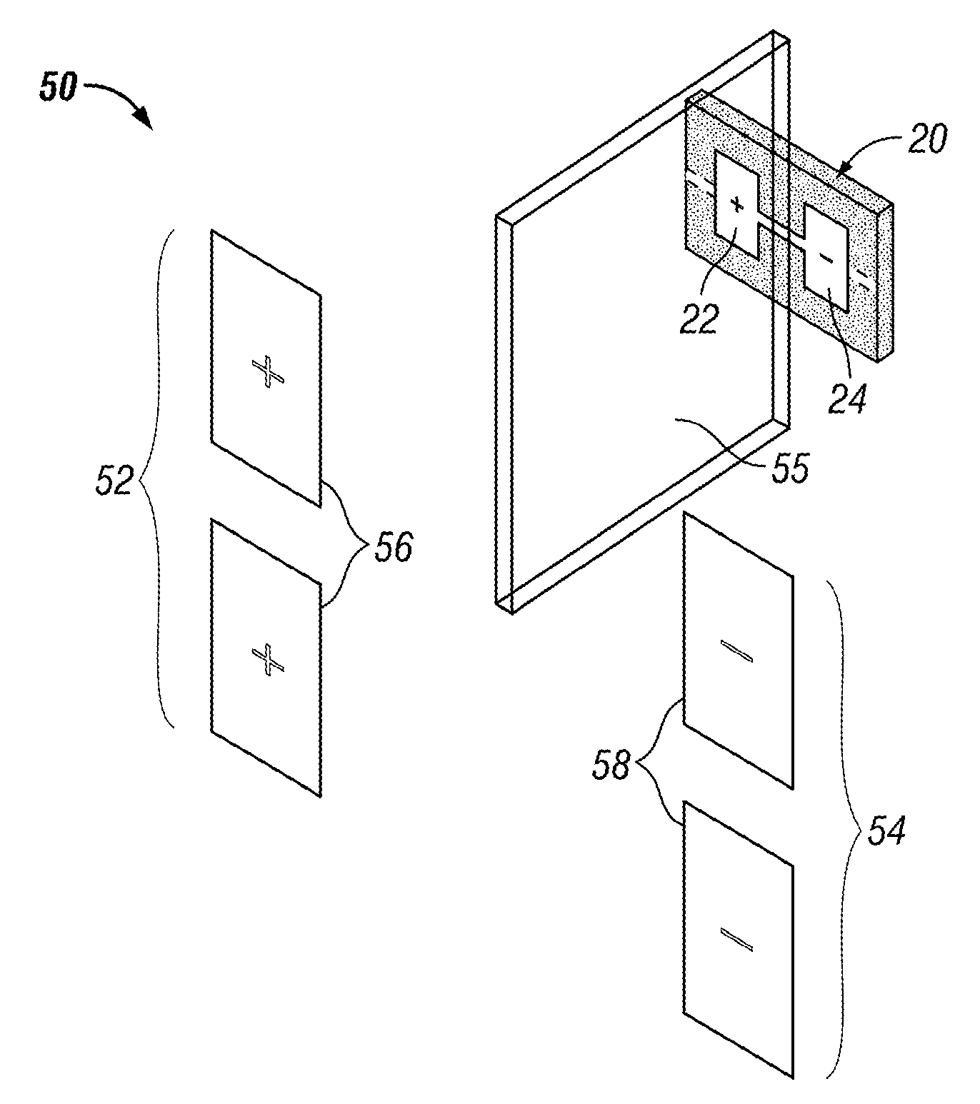
[0040]Certain embodiments as disclosed herein provide for a PIR curtain motion sensor system in which a dual-element IR detector with opposite polarity detector elements has separate, independently oriented lenses or optical elements associated with the respective detector elements, where each lens can be angled individually relative to the respective detector element so as to control the spacing between the monitored volumes and thus the width of the “curtain” or set of monitored volumes, without varying the spacing between the respective lenses and the detector elements.

[0041]After reading this description, it will become apparent to one skilled in the art how to implement the invention in various alternative embodiments and alternative applications. However, although various embodiments of the present invention will be described herein, it is understood that these embodiments are presented by way of example only, and not limitation. As such, this detailed description of various a...


PUM


Abstract

An infrared motion sensor has a multi element IR detector with first and second separate arrays of optical elements associated with respective first and second detector elements and a partition of a material substantially opaque to IR radiation and substantially transparent to visible / NIR light arranged to separate the IR optical paths from the first and second optical elements to the respective first and second detector elements. In this way, the detector elements function individually with respect to IR radiation and individual optical elements produce separate and independently oriented fields of view on the first and second sides of the sensor, while visible / NIR light still falls on both detector elements so that detector element signals resulting from NIR radiation roughly cancel one another.

Description

RELATED APPLICATION[0001]The present application claims the benefit of U.S. provisional Pat. App. Ser. No. 61 / 279,968, filed Oct. 29, 2009, the contents of which are incorporated herein by reference in their entirety.BACKGROUND[0002]1. Field of the Invention[0003]The present invention relates generally to passive infrared (PIR) motion sensors.[0004]2. Related Art[0005]Passive infrared motion sensors generally consist of several features. An optical element (such as a lens or mirror) and an infrared (IR) detector together define and collect radiation from a field-of-view (intersecting and thus defining a monitored spatial volume), from which the optical element conveys radiation onto an infrared (IR) detector which is generally responsive to mid-IR light in the 6-14 micron wavelength range. The detector, in turn, provides an electrical signal responsive to changes in the effective blackbody temperature of the surfaces of objects within the monitored volume and radiating toward the op...

Claims


Application Information

Patent Timeline
Patent Type & Authority Patents(United States)
IPC IPC(8): G01J5/02
CPCG01J5/0022G01J5/0025G01J5/089G01J5/0846G01J5/08G01J5/07
Inventor MICKO, ERIC S.
Owner SUREN SYST
Why Eureka
Try Eureka