Polystyrene wall, system, and method for use in an insulated foam building

a polystyrene wall and insulating foam technology, applied in the field of residential structures, can solve the problems of increasing the cost of heating and cooling in the winter, difficult to cool in the summer, and the method being used to build icf residential structures, and achieve the effect of giving structure strength

Active Publication Date: 2013-01-29
SOLID GREEN SYST +1
View PDF11 Cites 38 Cited by
  • Summary
  • Abstract
  • Description
  • Claims
  • Application Information

AI Technical Summary

Benefits of technology

[0013]It is yet another object of the present invention to use precut polystyrene panels to form walls on a foundation of a residential structure, which wall columns may then be poured with concrete to give structure strength.
[0014]It is yet another object of the present invention to design each panel of polystyrene that may be cut in the factory and delivered to the job site for construction into the building of an ICF residential structure with a minimum amount of labor being required at the job site.

Problems solved by technology

One of the problems with a wood framed house, with or without stone, is that it was expensive to heat in the winter and hard to cool in the summer.
However, fundamental problems still revolve around the methods being used to build ICF residential structures.
The first major problem is the prior systems require a lot of labor in the shaping, cutting or modifying the foam blocks for the particular structure.
A second problem is that after cutting, shaping or modifying the foam structure, the foam structure loses much of its insulating value.
Third, the insulating foam does not have the structural integrity so enough concrete must be used therewith to give the strength necessary for the structure.
While each has its own advantages and pit falls, the major problem is the expense involved in building the structures.
If the expense is held down, normally the buildings do not have the structural integrity.

Method used


Image

  • Polystyrene wall, system, and method for use in an insulated foam building
  • Polystyrene wall, system, and method for use in an insulated foam building
  • Polystyrene wall, system, and method for use in an insulated foam building

Examples


Embodiment Construction

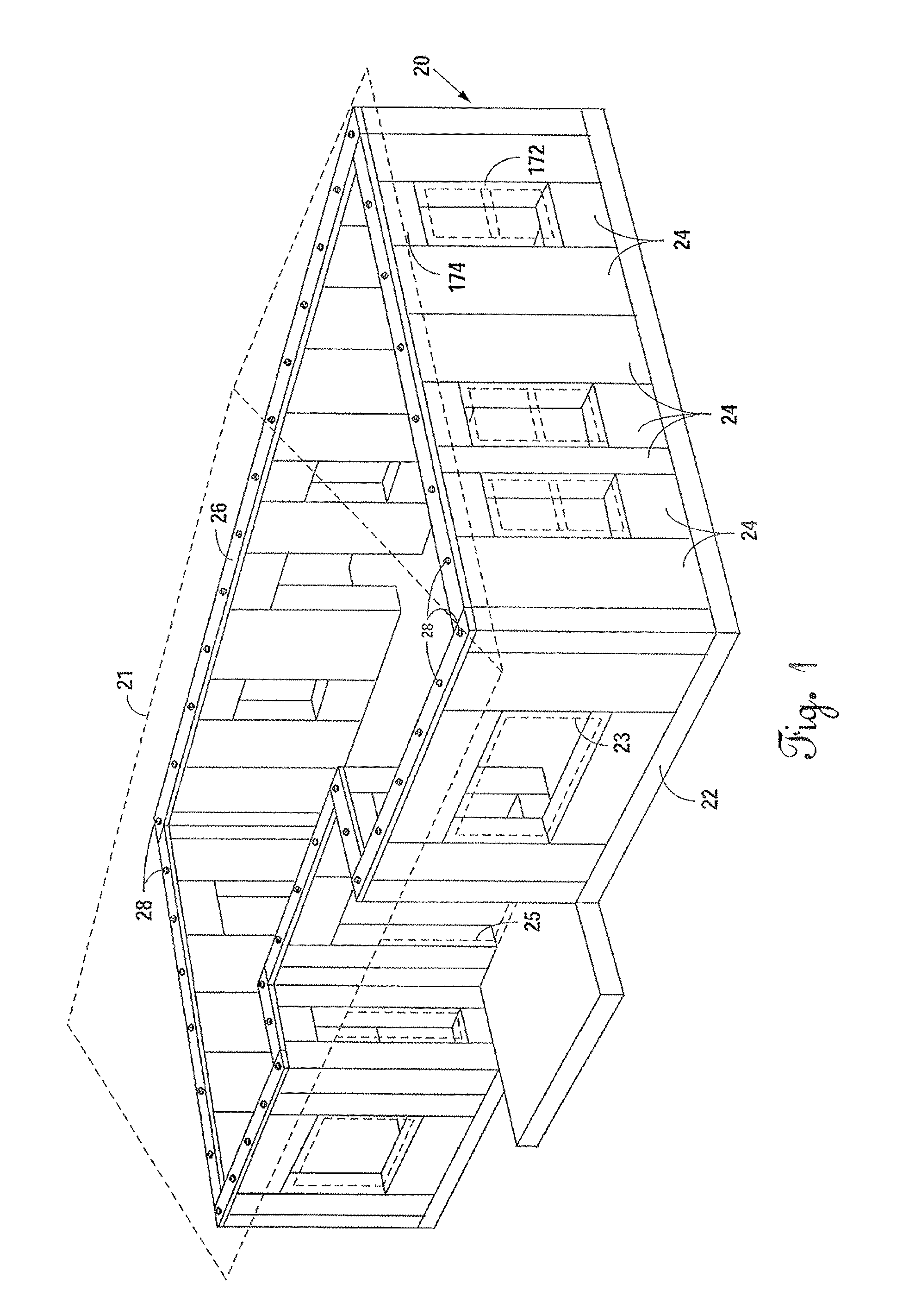
[0041]Referring now to FIG. 1 of the drawings, a frame 20 for a residential structure is located on a foundation 22 and has a roof structure 21 attached thereto. The foundation 22 is typically made of reinforced concrete. The frame 20 has a series of wall panels making up the frame 20, each of the wall panels 24 being separately designed for the particular residence. The frame 20 has windows 23 and doors 25 therein as would be found in most residences. The top of the frame 20 is capped off by a 2×12 board 26 that is held in position by J bolts 28. The frame 20 and the panels 24 making up the frame will be discussed in further detail hereinbelow.

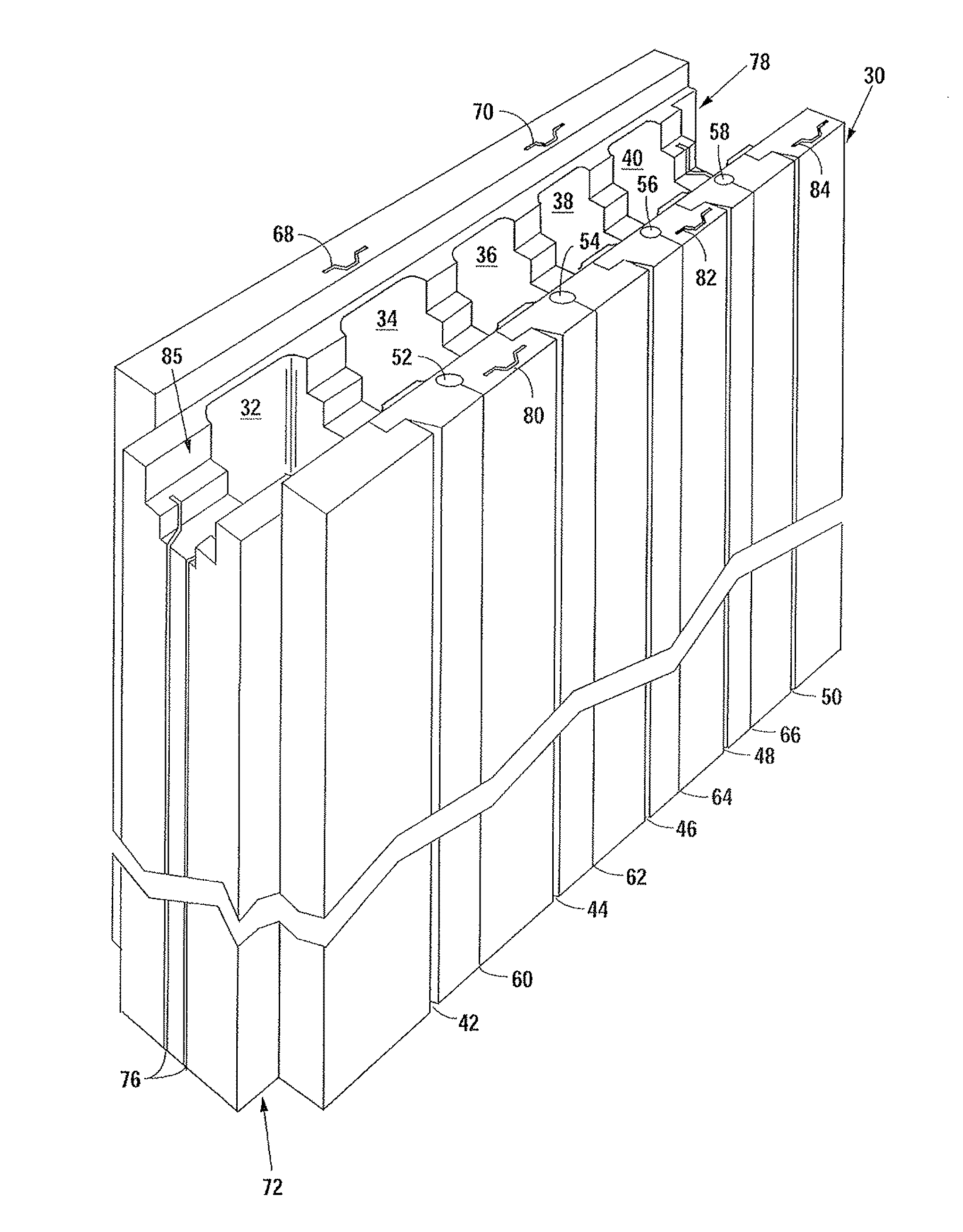
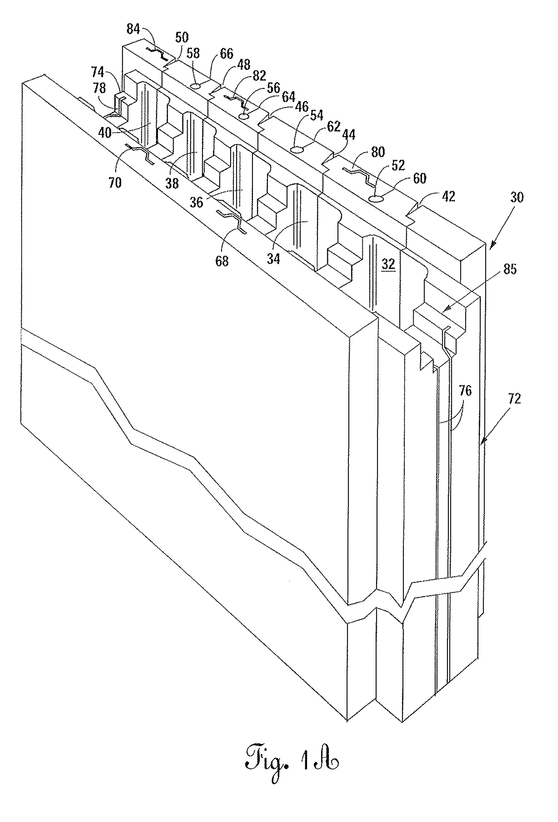
[0042]Foam, whether polystyrene or some other type expanded foam, is typically delivered in blocks that are 8 ft.×8 ft.×16 ft. These blocks are cut into pieces with the largest piece being 4 ft.×1 ft.×8 ft. Since the 8 foot length represents the ceiling height, sometime that may vary and may be up to 9 ft in height. Typically if a 9 ft. ceili...


PUM

PropertyMeasurementUnit
heightaaaaaaaaaa
lengthaaaaaaaaaa
lengthaaaaaaaaaa

Abstract

The present invention uses insulating concrete forms (ICF) in the construction of residential buildings. An entire wall panel is formed from polystyrene panels that may be cut by a hot wire machine. If necessary, hat channel shaped metal may be inserted into hat channel slots. Columns of polystyrene are removed so that concrete posts may be poured therein after the wall panel has been secured into place with rebar being located therein. Rebar and concrete also are formed along the top of the wall panel. Electrical and plumbing connection pathways are provided in the wall panel at the time of cutting with hot wire. Each wall panel is separately designed and cut by hot wire while still at the factory, but are all connected together to form an ICF residence. Openings are provided for doors and windows and are buck framed. Hat channels are inserted as necessary for strength and / or connection thereto.

Description

BACKGROUND OF THE INVENTION[0001]1. Field of the Invention[0002]The present invention relates to a system and method of building a residential structure and, more particularly, to a residential structure having insulated concrete forms (hereinafter referred to as “ICF”) that are used in forming the walls, which walls are attached to a concrete slab and to a roof.[0003]2. Background of the Prior Art[0004]As this country was being settled, early pioneers built homes from whatever was available. In the areas having a lot of trees, the homes were normally made out of logs. In other areas that were rocky, homes were made out of rock. As the plains area of the country was settled, homes were made out of sod. In arid regions, homes were made out of stucco or were even dug into the sides of hills or cliffs.[0005]As time passed and this country was settled, the building of residential structures evolved to the use of wood frames. Sometimes precut stone or brick would also be used, but normal...

Claims


Application Information

Patent Timeline
Patent Type & Authority Patents(United States)
IPC IPC(8): E04B1/00
CPCE04B1/165E04C1/397E04C2/205E04C2/521E04G21/185E04G21/26E04B2/8629E04B2002/867E04B2002/8688
Inventor STEPHENS, JR., ROY DEAN
Owner SOLID GREEN SYST
Why Eureka
Try Eureka