Puncture aid with protection against reuse
a puncture aid and reuse technology, applied in the field of disposable puncture aids, can solve the problems of user contamination or infected by blood residue, unpreventable and inability to use a tool again to tension the puncture aid, so as to prevent reuse of puncture aids
- Summary
- Abstract
- Description
- Claims
- Application Information
AI Technical Summary
Benefits of technology
Problems solved by technology
Method used
Image
Examples
first embodiment
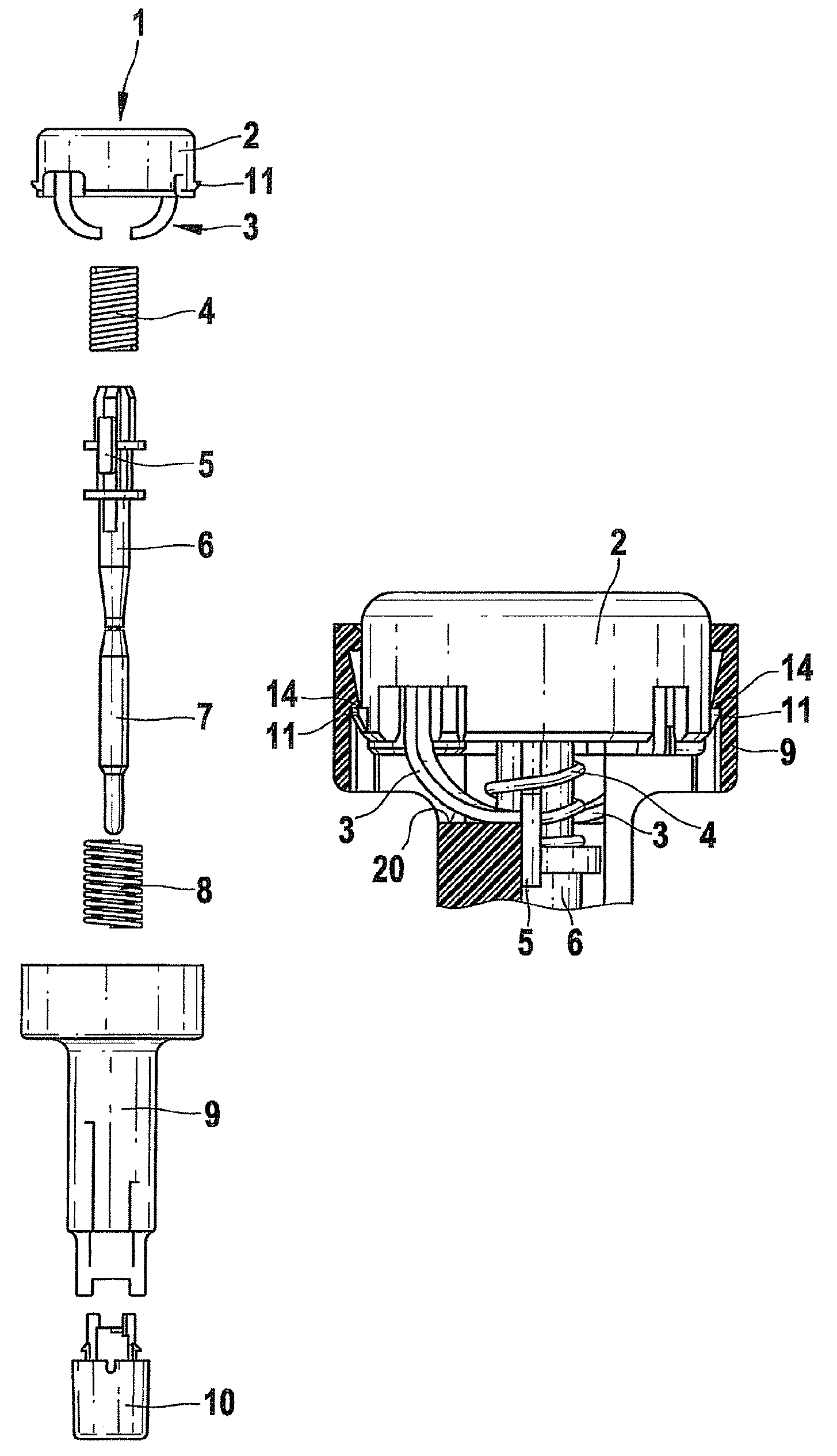
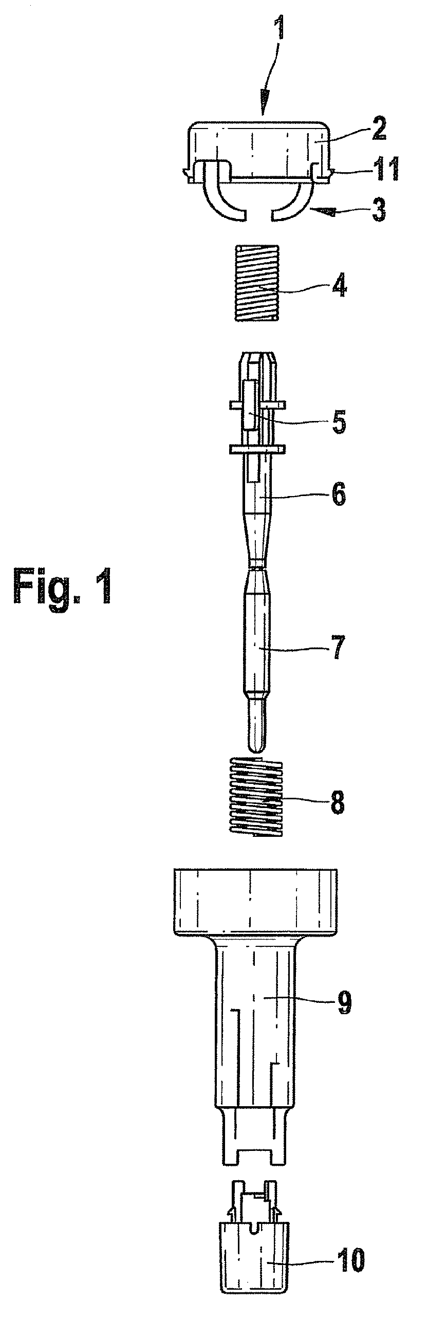
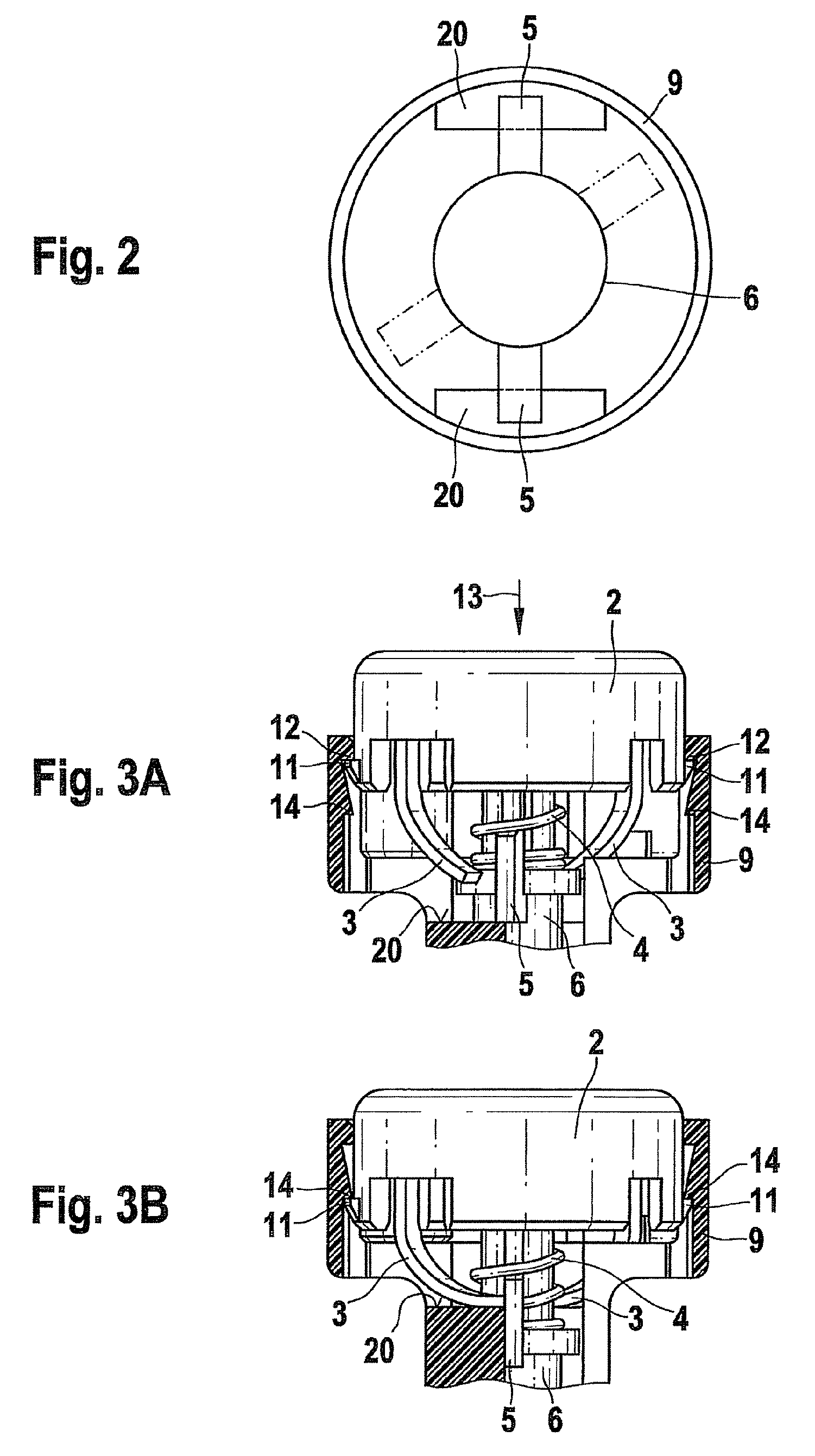
[0044]FIG. 3A shows a sectional detail of a puncture aid before the first use. The trigger is shown with its two hooks 11. Before use of the puncture aid, the hooks 11 are hooked behind two upper projections 12 of the housing 9, so that the trigger is locked in the housing 9 above lower projections 14 of the housing 9. Small hooks3 acting as rotary drive elements are connected to the trigger button 2. In the illustrated position of the trigger button 2 (not pressed down), the small hooks 3 are spaced apart from the bearing elements 5 of the lancet holder 6, which in the first position rest on the support surfaces 20 (not shown). The drive spring 4 is in a tensioned (compressed) state. When the trigger button 2 is pressed in the axial direction 13, the trigger button 2 executes a linear movement in the axial direction. In this way, the rotary drive elements 3 are pressed against the bearing elements 5, which consequently execute a rotation movement relative to the support surfaces 20...
second embodiment
[0047]FIG. 4A shows a puncture aid before its use. The trigger button 2 of this puncture aid has two hooks 11 which hook the trigger button 2 in each case in a recess 15 of the housing 9, so that the trigger button 2 cannot be detached from the housing 9. In the puncture aid shown in FIG. 4A, the bearing elements 5 of the lancet holder 6 rest on the support surfaces 20 (not shown), and the rotary drive elements 3 (small hooks) are spaced apart from the bearing elements 5.
[0048]When the trigger button 2 is pressed down in order to trigger a puncturing process, the bearing elements 5 are displaced from the support surfaces 20 by the rotary drive elements 3 and fall into the guide grooves 25. The hooks 11 each slide through a housing opening 16 until they emerge from the housing 9 and hook in behind an edge 17 on the outside of the housing 9. This hooked position is shown in FIG. 4B. The rotary drive elements 3 are positioned on the support surfaces 20 (not shown), so that they serve a...
third embodiment
[0049]FIG. 5A shows an unused puncture aid. The trigger button 2 of this puncture aid has four hooks, namely two lower hooks 18 and two upper hooks 19. In the position shown in FIG. 5A, the lower hooks 18 are hooked in behind projections 21 on the upper edge of the housing 9, so that the trigger button 2 is held securely on the housing. The rotary drive elements 3 designed as small hooks are arranged spaced apart from the bearing elements 5 that rest on the support surfaces 20 (not shown).
[0050]By pressing the trigger button 2 down, the latter is displaced linearly in the axial direction 13. The rotary drive elements 3 are pressed against the bearing elements 5, so that the lancet holder 6 executes a rotation movement and the bearing elements 5 fall from the support surfaces 20 (not shown) into the guide grooves 25. The lancet then executes a puncturing movement. As is shown in FIG. 5B, the trigger button 2 is hooked with the upper hook 19 behind the projections 21 after the linear ...
PUM
 Abstract
Description
Claims
Application Information
 - R&D
- Intellectual Property
- Life Sciences
- Materials
- Tech Scout
- Unparalleled Data Quality
- Higher Quality Content
- 60% Fewer Hallucinations
Browse by: Latest US Patents, China's latest patents, Technical Efficacy Thesaurus, Application Domain, Technology Topic, Popular Technical Reports.
© 2025 PatSnap. All rights reserved.Legal|Privacy policy|Modern Slavery Act Transparency Statement|Sitemap|About US| Contact US: help@patsnap.com


