Supercharge Your Innovation With Domain-Expert AI Agents!

Video surveillance method and system based on average image variance

a video surveillance and average image technology, applied in the field of video surveillance methods and systems, can solve the problems of escaping operators' attention, powerful and costly computing means,

Active Publication Date: 2013-01-29
STMICROELECTRONICS SRL
View PDF20 Cites 2 Cited by
  • Summary
  • Abstract
  • Description
  • Claims
  • Application Information

AI Technical Summary

Problems solved by technology

The result is that intrusions can escape the operators' attention.
Such systems require powerful and costly computing means so that the image can be analyzed in real time with sufficient reliability.

Method used


Image

  • Video surveillance method and system based on average image variance
  • Video surveillance method and system based on average image variance
  • Video surveillance method and system based on average image variance

Examples


Embodiment Construction

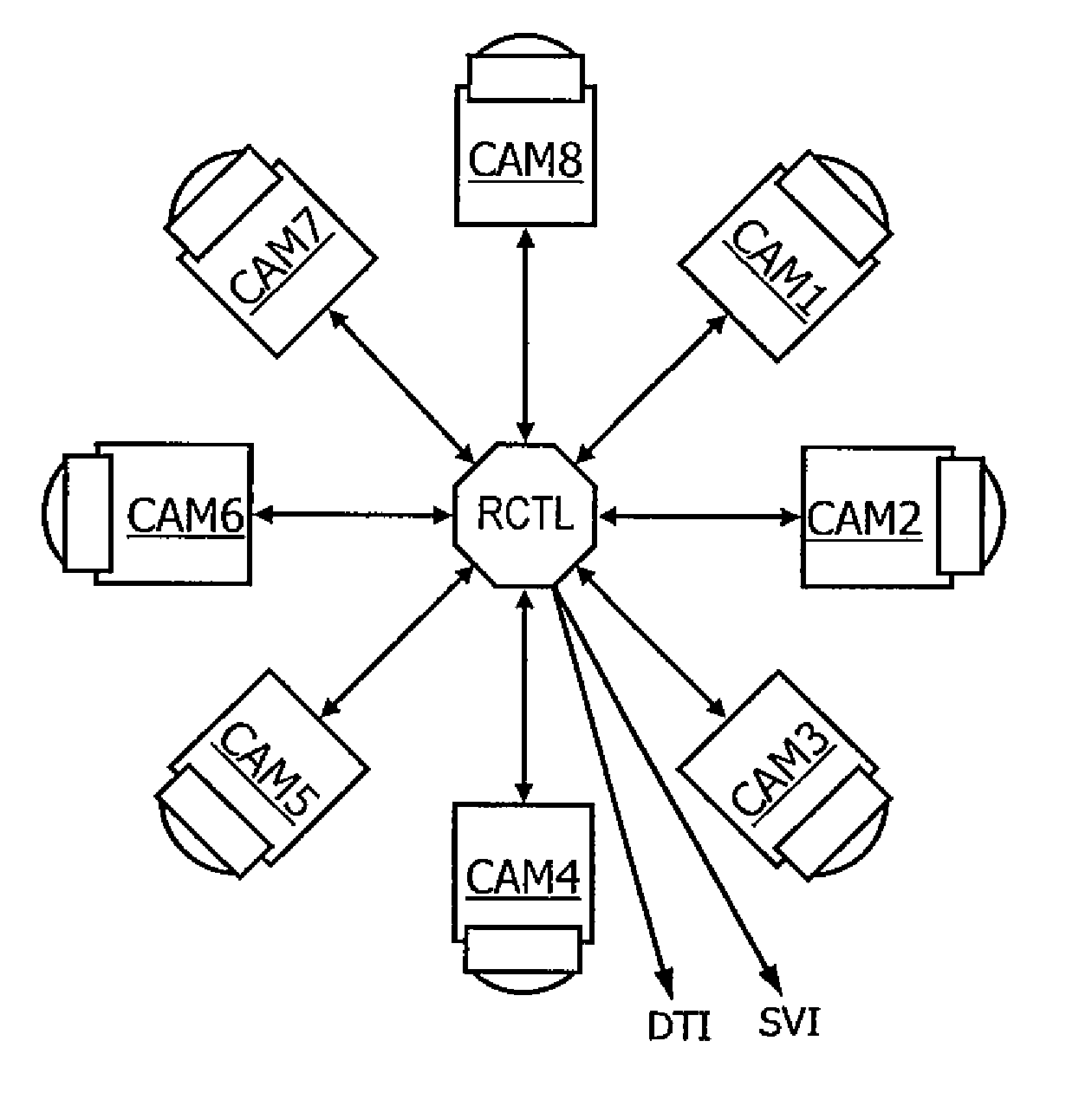
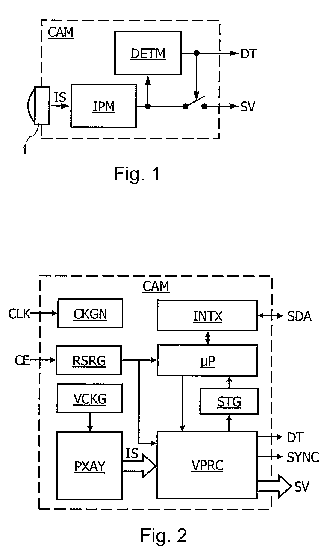
[0039]FIG. 1 represents a presence detection system comprising a video camera module CAM. The module CAM comprises a digital image sensor 1, an image processing module IPM and a detection module DETM. The sensor 1 supplies the module IPM with image signals. Using the image signals, the module IPM produces a flow of video frames or digital images SV. The module DETM analyzes the images SV supplied by the module IPM and generates a detection signal DT indicating whether or not any presence has been detected in the images SV. The signal DT controls the transmission of the flow of images SV at output of the module CAM. The image sensor 1 can be of CMOS type.

[0040]FIG. 2 represents one embodiment of the video camera module CAM which can be produced as a single integrated circuit. In FIG. 2, the module CAM comprises the sensitive surface PXAY of the image sensor 1, a clock signal generator CKGN, an interface circuit INTX, a microprocessor μP, a video processing circuit VPRC, a video synch...


PUM


Abstract

The present disclosure relates to a video surveillance method comprising steps of a video camera periodically capturing an image of a zone to be monitored, analyzing the image to detect a presence therein, and of the video camera transmitting the image only if a presence has been detected in the image.

Description

BACKGROUND[0001]1. Technical Field[0002]The present disclosure relates to a video surveillance method and system. The present disclosure applies in particular to the detection of presence or intrusion.[0003]2. Description of the Related Art[0004]Video surveillance systems generally comprise one or more video cameras linked to one or more screens. The screens need to be monitored by one or more human operators. The number of video cameras can be greater than the number of screens. In this case, the images of a video camera to be displayed on a screen must be selected either manually or periodically.[0005]These systems require the constant attention of the operator who must continuously watch the screens so as to be able to detect any presence or intrusion. The result is that intrusions can escape the operators' attention.[0006]Image processing systems also exist which enable the images supplied by one or more video cameras to be analyzed in real time to detect an intrusion. Such syst...

Claims


Application Information

Patent Timeline
Patent Type & Authority Patents(United States)
IPC IPC(8): H04N7/18
CPCG08B13/19602G08B13/19641G08B13/19652
Inventor MARTIN, LIONELBAUDON, TONY
Owner STMICROELECTRONICS SRL
Features
  • R&D
  • Intellectual Property
  • Life Sciences
  • Materials
  • Tech Scout
  • Unparalleled Data Quality
  • Higher Quality Content
  • 60% Fewer Hallucinations
Learn More