Ink-jet recording apparatus

a recording apparatus and inkjet technology, applied in typewriters, printing, other printing apparatus, etc., can solve the problems of inability to carry out continuous printing, lack of method productivity, blurred image, etc., to achieve suppressed blue image, suppressed contamination of adjacent units, and suppressed contamination of recording media

Active Publication Date: 2013-02-12
MIYAKOSHI PRINTING MACHINERY
View PDF1 Cites 4 Cited by
  • Summary
  • Abstract
  • Description
  • Claims
  • Application Information

AI Technical Summary

Benefits of technology

[0023]In the ink-jet recording apparatus of the present invention, the first surface of the recording medium is subjected to printing in the first unit and then dried by the first drying drum, and the second surface of the recording medium is subjected to printing in the second unit and then dried by the second drying drum. Therefore, even in the case of a print design that requires a large amount of ink application, blur of the image is suppressed since the recording medium is dried by the drying drums. Moreover, since the first unit and the second unit are adjacent to each other, printing can be carried out continuously onto both surfaces of the recording medium by the path from which an unnecessary part is eliminated as much as possible.
[0024]In the above described ink-jet recording apparatus, the first surface is configured to be subjected to printing in the first unit while the recording medium travels from the second unit side toward the opposite side, and the second surface is configured to be subjected to printing in the second unit while the recording medium travels from the first unit side toward the opposite side; consequently, an accompanying current generated upon traveling of the recording medium involves the vaporous floating ink floating in the air and brings the floating ink to the opposite side of the unit. Therefore, contamination of the adjacent unit can be suppressed. When the walls are provided between the first unit and the second unit, contamination of the recording medium can be reliably suppressed.
[0025]When the suction device is attached to each of the entrance-side sidewall of the first frame wall of the first unit and the exit-side sidewall of the second frame wall of the second unit, the floating ink is sucked in by the suction devices, thereby reliably suppressing the contamination caused by the floating ink.
[0026]In the above described ink-jet recording apparatus, the installation space can be downsized by disposing the drying drums below the ink-jet recording heads. Thus, the housing space can be provided between the first drying drum and the second drying drum. For example, when the first unit and the second unit both have the shape of a turned L, a wider housing space can be provided.
[0027]In the housing space, auxiliary equipment such as ink tanks and a control board can be disposed.
[0028]In the above described ink-jet recording apparatus, when the first ink-jet recording head and the second ink-jet recording head are provided at the same height, uniform operability and workability can be ensured. When the constitutions thereof are also the same, assembly is easy, and production cost of the parts thereof can be reduced.

Problems solved by technology

However, in this batch-type method, if the medium is not dried once, the image thereon may be blurred since a large amount of ink has to be applied depending on the design thereof.
Therefore, continuous printing cannot be carried out, and the method lacks productivity.

Method used


Image

  • Ink-jet recording apparatus
  • Ink-jet recording apparatus
  • Ink-jet recording apparatus

Examples


Embodiment Construction

[0033]Hereinafter, a preferred embodiment of the present invention will be explained in detail with reference to the drawings if needed. Note that, in the drawings, the same elements are denoted by the same reference numerals, and redundant explanations thereof are omitted. Moreover, unless otherwise stated, the positional relations such as top, bottom, left, and right are based on the positional relations shown in the drawings. Furthermore, the dimensional ratios of the drawings are not limited to the ratios shown in the drawings.

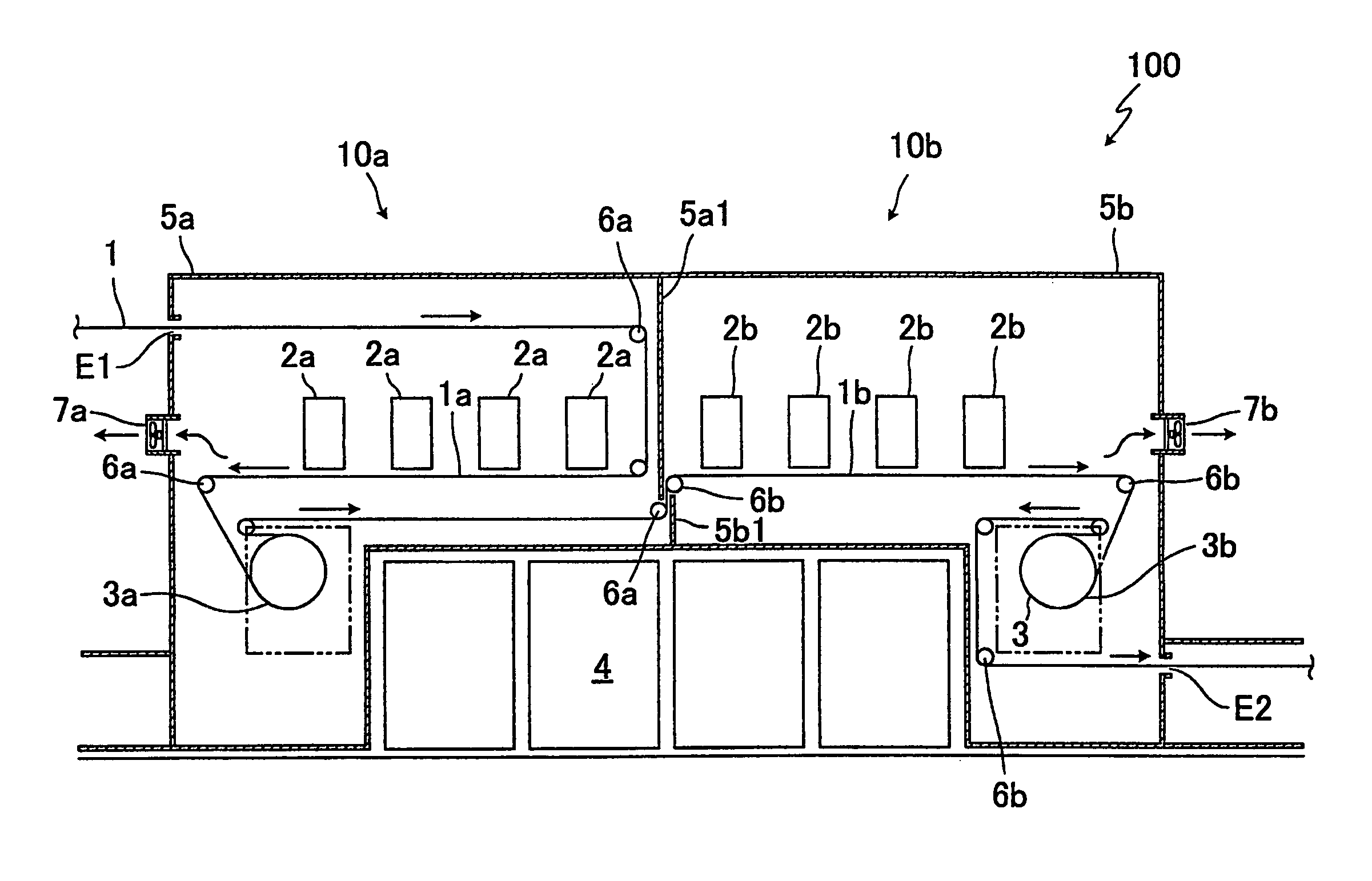
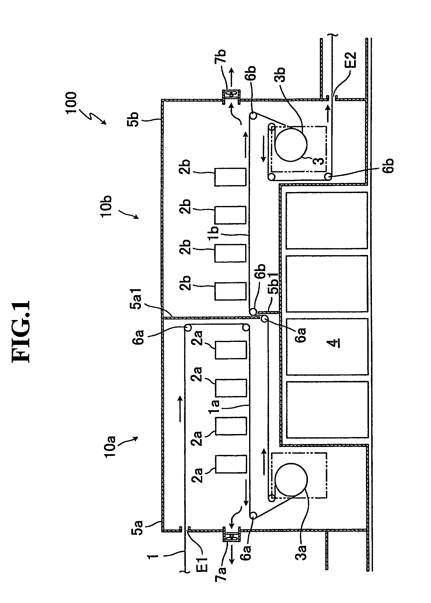
[0034]FIG. 1 is a schematic drawing showing an example of an ink-jet recording apparatus according to a present embodiment.

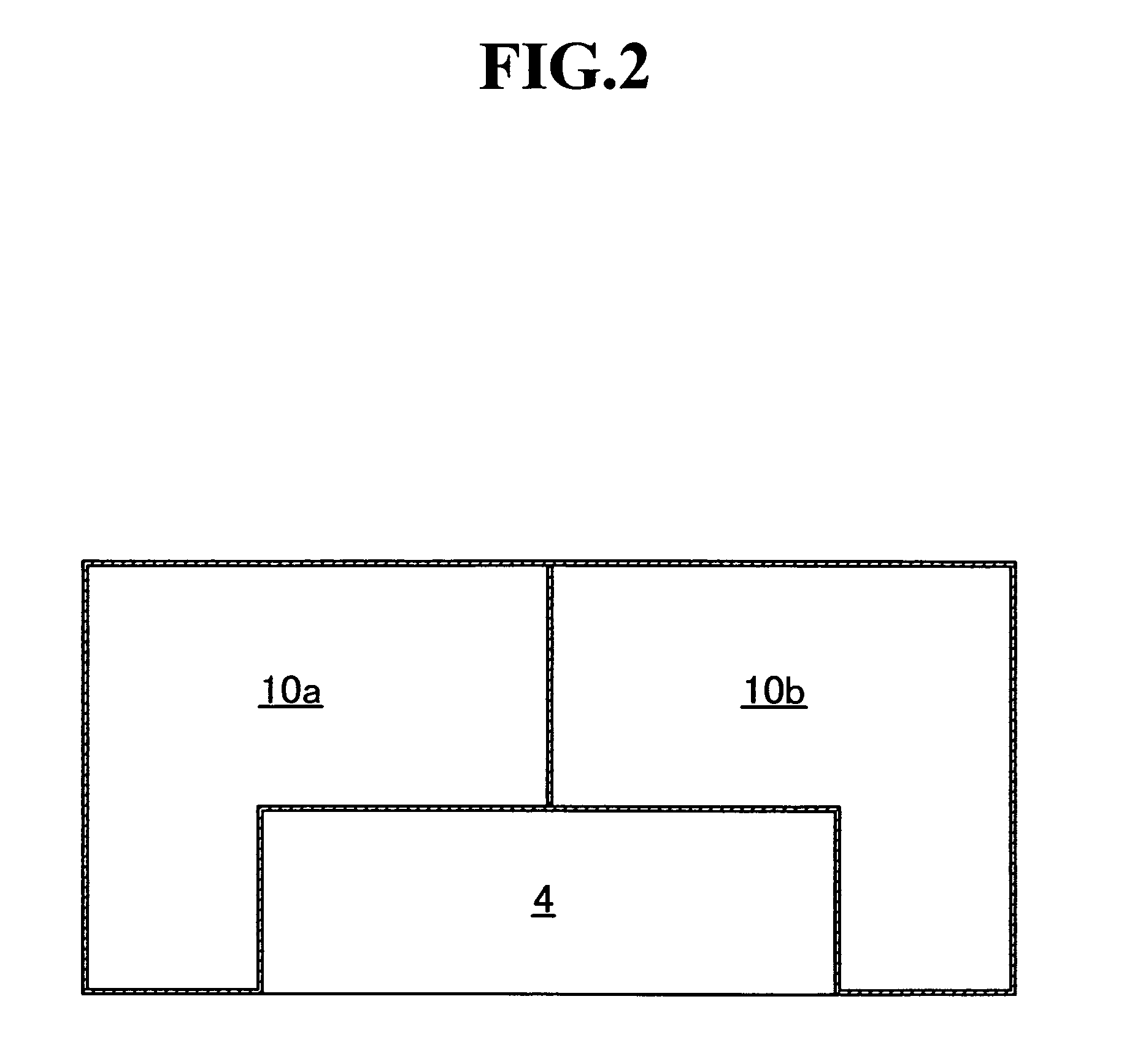
[0035]As shown in FIG. 1, the ink-jet recording apparatus 100 of the present invention has a first unit 10a for carrying out printing onto a first surface 1a of a recording medium 1 and a second unit 10b for carrying out printing onto a second surface 1b of the recording medium 1. Therefore, according to the above described ink-jet rec...


PUM


Abstract

The present invention is an ink-jet recording apparatus 100 capable of carrying out printing continuously onto both surfaces of a recording medium 1, the ink-jet recording apparatus 100 having: a first unit 10a having a first ink-jet recording head 2a for carrying out printing onto a first surface la of the recording medium 1 and having a first drying drum 3apositioned below the first ink-jet recording head 2a and heating and drying the recording medium 1 after the printing; and a second unit 10b having a second ink-jet recording head 2b for carrying out printing onto a second surface 1b of the recording medium 1 and having a second drying drum 3b positioned below the second ink-jet recording head 2b and heating and drying the recording medium 1 after the printing.

Description

TECHNICAL FIELD[0001]The present invention relates to an ink-jet recording apparatus and, more particularly, relates to an ink-jet recording apparatus capable of suppressing the contamination of a recording medium, efficiently utilizing installation space, and carrying out continuous printing onto both surfaces of the recording medium.BACKGROUND ART[0002]Generally, an ink-jet recording method is used in many fields since desired designs and characters can be printed.[0003]Recently, a recording medium having both surfaces on which designs or characters are printed by the ink-jet recording method is desired.[0004]Examples of the method of carrying out printing on both surfaces of a recording medium by the ink-jet recording method include a batch-type method in which printing is carried out twice by the same ink-jet recording apparatus.[0005]In this method, for example, printing is carried out on one of the surfaces of the recording medium by the ink-jet recording method, the recording...

Claims


Application Information

Patent Timeline
Patent Type & Authority Patents(United States)
IPC IPC(8): B41J2/01
CPCB41J3/60B41J29/13B41J15/04B41J11/002B41J11/0024
Inventor IZAWA, HIDEOISHIKAWA, AKIRA
Owner MIYAKOSHI PRINTING MACHINERY
Why Eureka
Try Eureka