
Developer, developer cartridge, developing device and image forming apparatus

a technology of image forming apparatus and developer cartridge, which is applied in the direction of developers, instruments, optics, etc., can solve the problems of difficulty in obtaining a toner having the desired flowability, and achieve the effect of suppressing phenomena

Active Publication Date: 2019-01-24
OKI ELECTRIC IND CO LTD
View PDF3 Cites 2 Cited by
  • Summary
  • Abstract
  • Description
  • Claims
  • Application Information

AI Technical Summary

Benefits of technology

The present invention aims to provide a developer that can prevent image blurring and ghosting. By using this configuration, the developer can suppress issues like image blurring, vertical streaking, or ghosting.

Problems solved by technology

However, in the toner of the above described document, the nitrogen-containing resin particle may easily separate from the surface of the colored resin particle, and may cause ghost.
Therefore, it is difficult to obtain a toner having a desired flowability (i.e.

Method used


Image

  • Developer, developer cartridge, developing device and image forming apparatus
  • Developer, developer cartridge, developing device and image forming apparatus
  • Developer, developer cartridge, developing device and image forming apparatus

Examples


Embodiment Construction

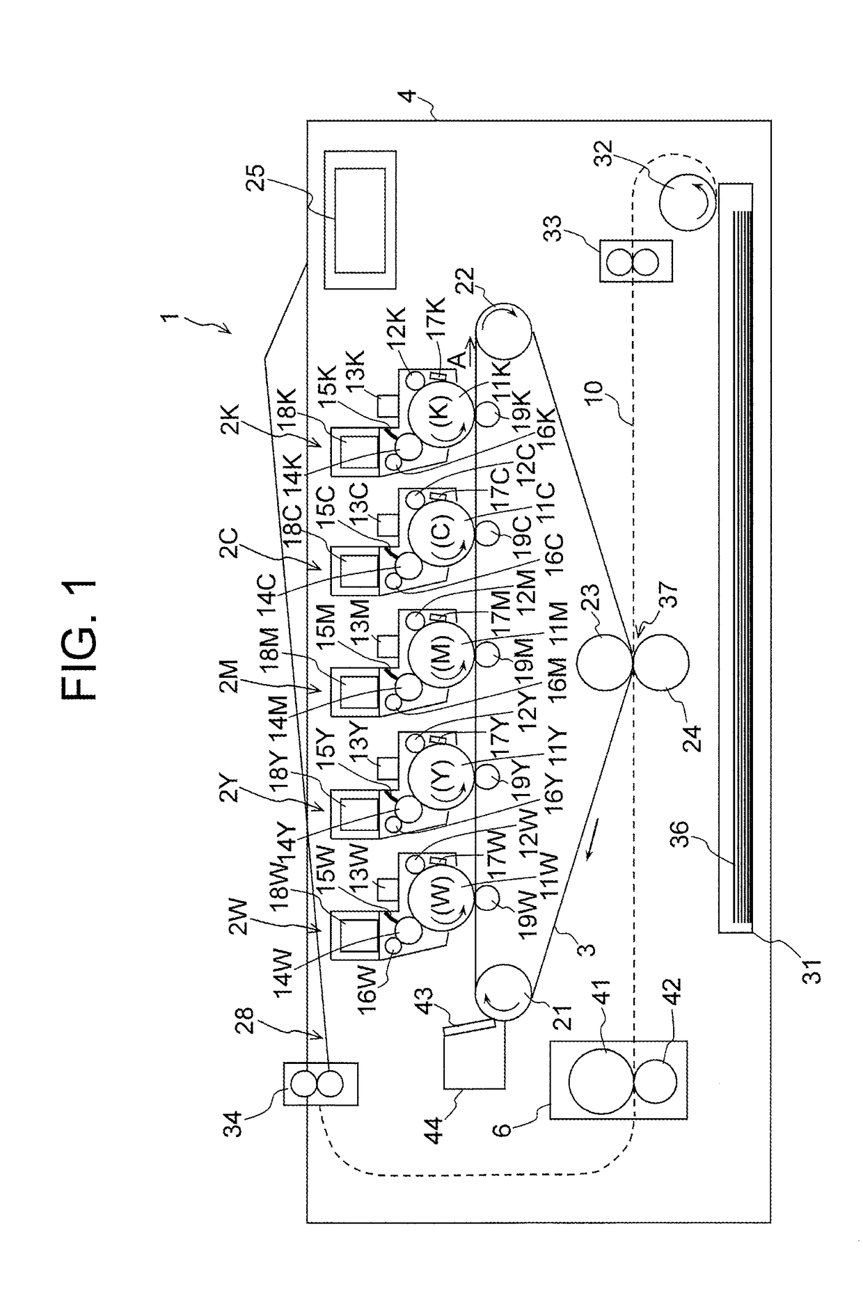
[0016]FIG. 1 is a schematic diagram showing a basic configuration of a printer 1 as an image forming apparatus of the embodiment of the present invention.

[0017]The printer 1 is configured as, for example, an electrophotographic color printer. To be more specific, the printer 1 has a configuration using a non-magnetic single-component development system (to be more specific, a non-magnetic single-component contact development system). The printer 1 includes five independent image forming units 2W, 2Y, 2M, 2C and 2K corresponding to white (W), yellow (Y), magenta (M), cyan (C) and black (K) disposed in a housing 4. The image forming units 2W, 2Y, 2M, 2C and 2K are arranged in this order along a moving direction (indicated by an arrow A) of an intermediate transfer belt 3. The image forming units 2W, 2Y, 2M, 2C and 2K may be referred to as image forming units 2 when there is no need to distinguish them from each other.

[0018]The image forming unit 2W is configured to form a toner image ...


PUM


Abstract

A developer including a colored resin particle and an external additive added to a surface of the colored resin particle and having a diameter smaller than or equal to 200 nm is provided. The external additive includes a nitrogen-containing resin particle. In elemental analysis of the nitrogen-containing resin particle, a peak appearing in a range of 0.38-0.42 keV is expressed as an N-peak, and a peak appearing in a range of 0.48-0.52 keV is expressed as an O-peak. Maximum count numbers in the N-peak and the O-peak of the external additive on a surface of the colored resin particle are respectively expressed as N1 and O1. Maximum count numbers in the N-peak and the O-peak of the surface of the colored resin particle where no external additive is observed are respectively expressed as N2 and O2. The count numbers N1, O1, N2 and O2 satisfy 1.7×(N2 / O2)<(N1 / O1).

Description

BACKGROUND OF THE INVENTION[0001]The present invention relates to a developer used in an electrophotographic image forming apparatus such as a copier, a facsimile machine, a printer or the like, and also relates to a developer cartridge, a developing device and the image forming apparatus.[0002]A general toner (developer) includes a colored resin particle and an external additive added to a surface of the colored resin particle. The external additive is formed of inorganic or organic substance, and is added in order to obtain a desired flowability and charging characteristics. The external additive contains, for example, a hydrophobic silica fine powder having a number-average primary particle diameter of 7-16 [nm], a colloidal silica fine powder having a number-average primary particle diameter of 65-100 [nm], and a nitrogen-containing resin particle having a number-average primary particle diameter of 200-300 [nm]. By using such a toner, a decrease in flowability of the toner duri...

Claims


Application Information

Patent Timeline
IPC IPC(8): G03G9/08G03G9/087G03G9/097G03G9/093
CPCG03G9/0819G03G9/0827G03G9/08782G03G9/09725G03G9/09733G03G9/09342G03G9/09708G03G9/09775G03G9/0821
Inventor KOJIMA, TAKESHI
Owner OKI ELECTRIC IND CO LTD
Learn More