Head-up display device

a display device and head-up technology, applied in the field of head-up display devices, can solve the problems of impaired display image (v) quality, and achieve the effects of reducing contact area, reducing twisting at the mirror holder portion, and improving display image quality

Active Publication Date: 2018-09-04
NIPPON SEIKI CO LTD
View PDF15 Cites 2 Cited by
  • Summary
  • Abstract
  • Description
  • Claims
  • Application Information

AI Technical Summary

Benefits of technology

[0020]In the invention according to claim 1, the stress acting on the mirror holder from the protruding piece when operating the position adjusting means is equalized in the lateral direction from the center of the mirror holder. The present invention does not concern the possibility of locally concentrating stress on a part of the mirror holder (mirror holder portion located near the second shaft portion) as in the conventional case. As a result, the twist (deformation) at the mirror holder portion is greatly suppressed, and accordingly, the driver can visually recognize the display image in which the distortion is suppressed, and there is an advantage that the display quality of the display image is improved.
[0021]In the invention according to claim 2, the first shaft portion and the steel ball contact each other at one point. In this way, the first shaft portion and the steel ball contact each other at one point, and the contact area becomes extremely small. As a result, abrasion of the first shaft portion that is in contact with the steel ball formed of the metal material at one point is suppressed, and there is an advantage that the durability of the first shaft portion can be improved.
[0022]In the invention according to claim 3, the protruding piece extending from the mirror holder is not just sandwiched between the first wall and the second wall, but is biased by the first and second leaf springs. Even if the inclination of the protruding piece is changed, no gap is formed between the protruding piece and the first and second leaf springs, and an axial force (a force for rotating the mirror holder about the rotation axis) is transmitted from the moving member to the protruding piece via the first and second walls and the first and second leaf springs. As a result, there is no worry that the mirror holder rattles, and occurrence of image blur of the display image can be suppressed.

Problems solved by technology

With the occurrence of the twist (deformation), there is a problem that the display image (V) visually recognized by the driver (14) through the windshield (13) is distorted and the display quality of the display image (V) is impaired.

Method used


Image

  • Head-up display device
  • Head-up display device
  • Head-up display device

Examples


embodiments

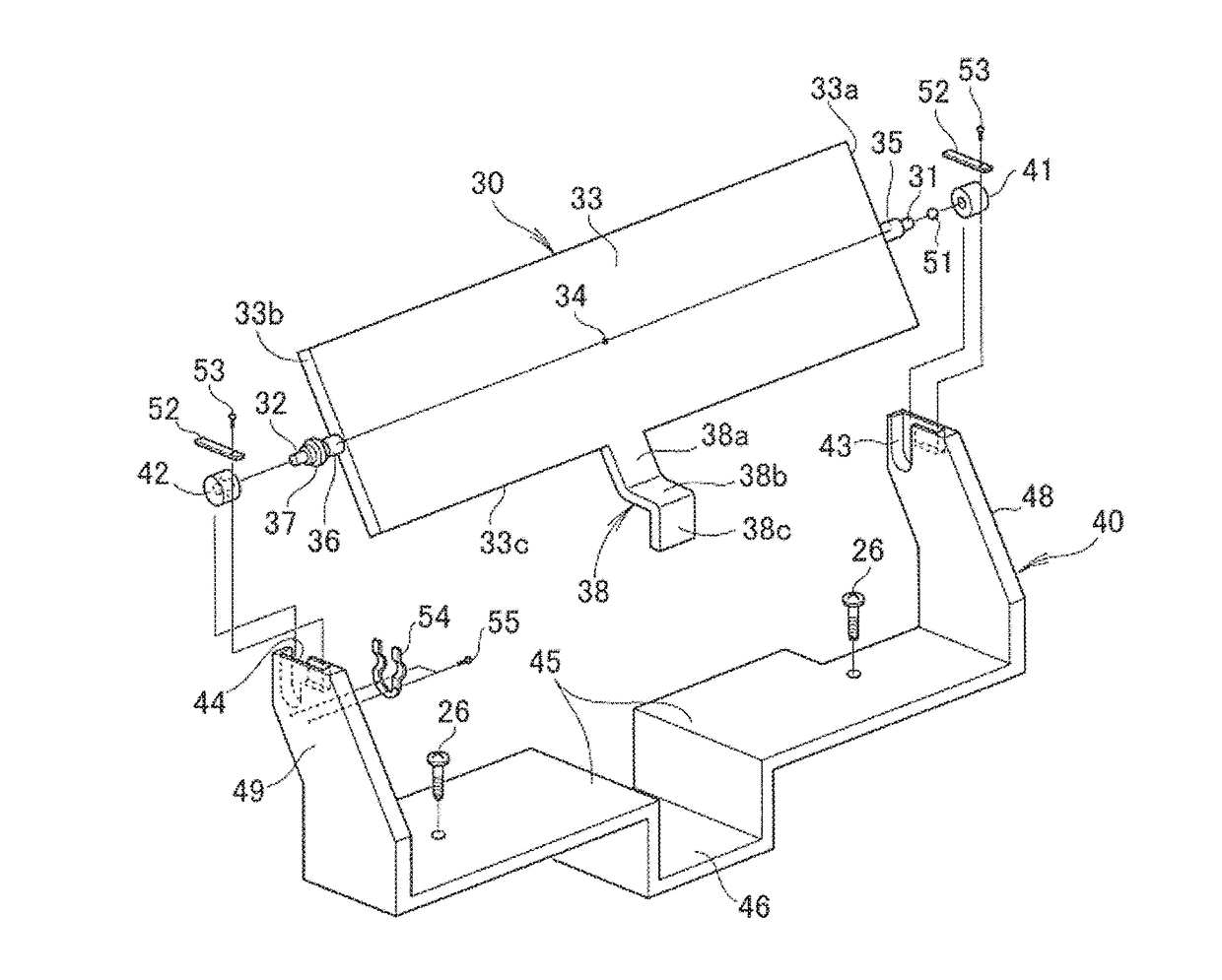
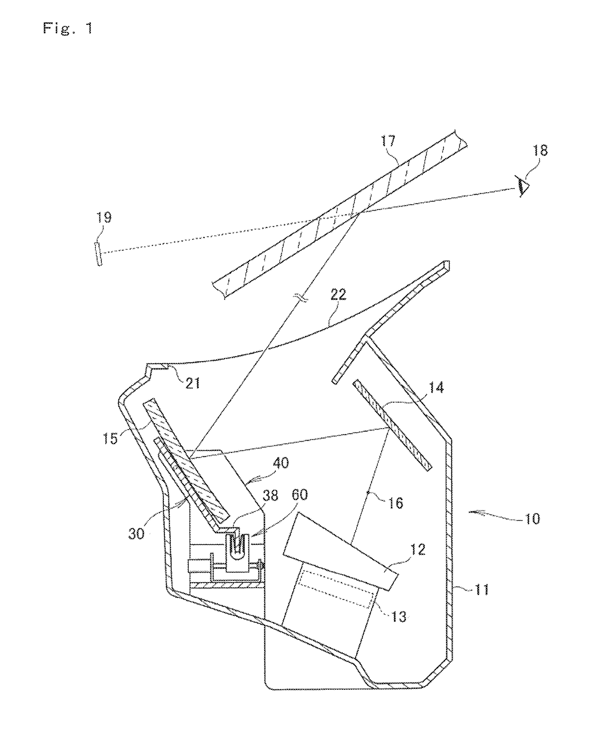
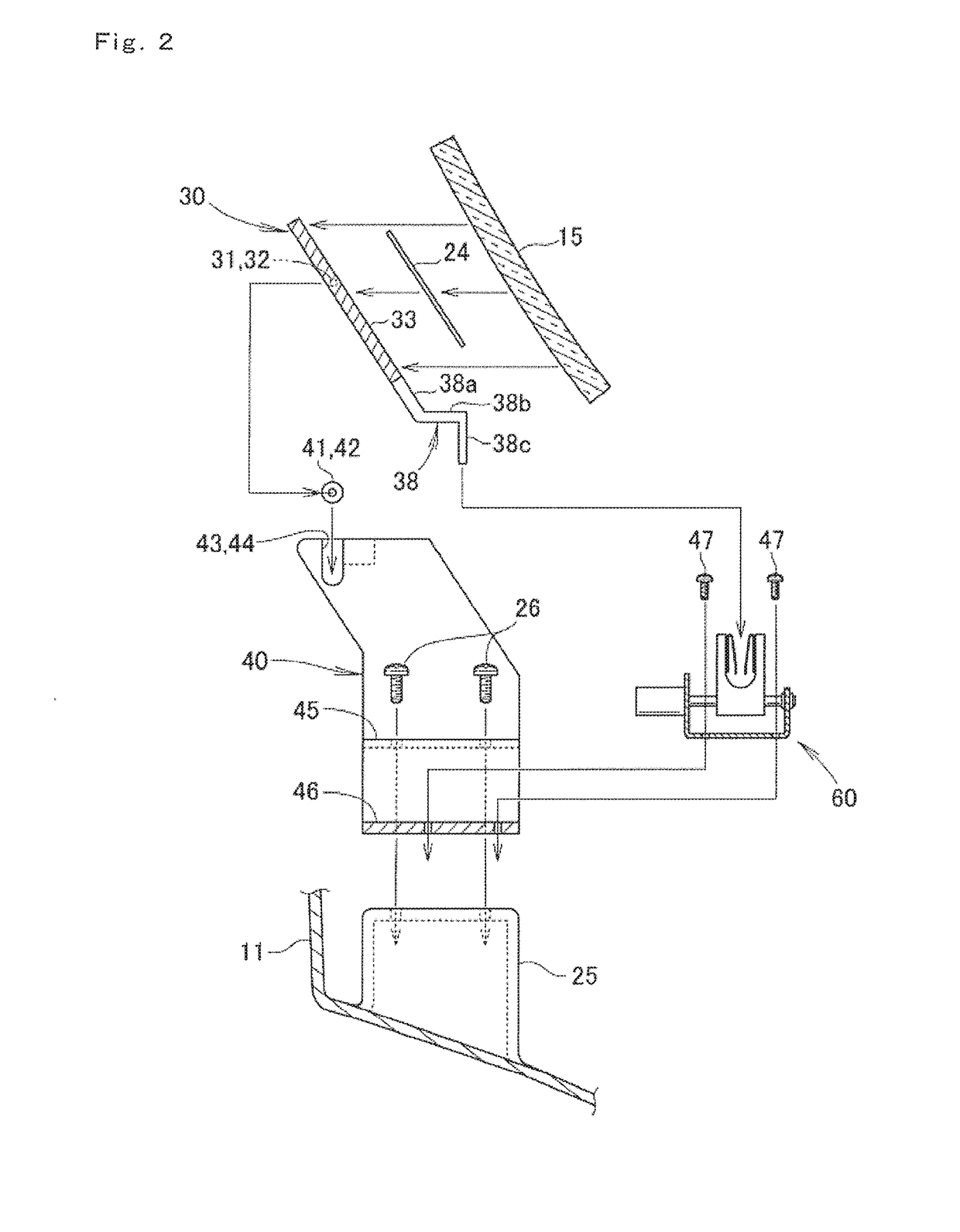
[0033]As shown in FIG. 1, the head-up display device 10 is mounted on a vehicle such as an automobile. The head-up display device comprises a housing 11, a display unit 12 and a backlight unit 13 housed in the housing 11, a plane mirror 14 and a concave mirror (reflection mirror) 15 housed in the housing 11, and a position adjusting means 60 housed in the housing 11 for adjusting the tilt angle of the concave mirror 15. The reflection mirror 15 may be not only a concave mirror, but also a plane mirror and other reflecting mirrors, and may be of any type and form.

[0034]The display unit 12 receives the light from the backlight unit 13, and generates display light 16. The generated display light 16 is reflected by the plane mirror 14, and the reflected light is reflected by the concave mirror 15.

[0035]That is, the display light 16, generated through the display unit 12 and the backlight unit 13 and reflected by the plane mirror 14 and the concave mirror 15, is irradiated onto a windshi...


PUM


Abstract

The present invention addresses the problem of providing a head-up display device with which the display quality of a display object can be improved. A mirror holder 30 supporting a concave mirror is equipped with a protruding piece that protrudes from the approximate center of the holder width, which is defined along a rotational axis, and this protruding piece is moved by a position adjustment means. Stress acting on the mirror holder from the protruding piece is uniform in the left and right directions from the center of the mirror holder. Consequently, twisting at the location of the mirror holder is significantly reduced, so the driver is able to view a display object for which distortion has been suppressed, and the display quality of the display object is improved.

Description

RELATED APPLICATIONS[0001]This application is the U.S. National Phase under 35 U.S.C. § 371 of International Application No. PCT / JP2015 / 084136, filed on Dec. 4, 2015, which in turn claims the benefit of Japanese Application No. 2014-249037, filed on Dec. 9, 2014, the disclosures of which are incorporated by reference herein.TECHNICAL FIELD[0002]The present invention relates to a head-up display device incorporating a concave mirror capable of tilting.BACKGROUND ART[0003]A driver of a vehicle gazes at the front through a windshield, and performs driving while visually checking instruments on an instrument panel. That is, a line of sight moves to the front and lower instruments. If a driver can see instruments while looking at the front, there is no movement of the line of sight, and improvement of drivability can be expected. From this finding, a head-up display device has been developed and put to practical use (see, for example, Patent Literature 1).[0004]As shown in FIG. 1 of Pate...

Claims


Application Information

Patent Timeline
Patent Type & Authority Patents(United States)
IPC IPC(8): G02B26/08G02B27/01B60K35/00
CPCG02B27/0149B60K35/00G02B27/0101G02B2027/0161B60K2350/2056G02B2027/0159B60K2350/2052B60K2370/334B60K2370/347B60K2370/1529B60K2370/23G02B27/01H04N5/74
Inventor USHIDA, NORIHIKOOKAMOTO, YOSHIYUKI
Owner NIPPON SEIKI CO LTD
Why Eureka
Try Eureka