Cyclonic separating apparatus for a cleaning appliance

a technology of separating apparatus and cleaning equipment, which is applied in the direction of liquid separation agent, filter regeneration, dispersed particle filtration, etc., can solve the problems of difficult to reliably seal the lower closure against the rest of the separating apparatus, and the sealing effect may become less effective with use, so as to reduce manufacturing tolerances and costs, the effect of effective sealing

Inactive Publication Date: 2013-02-19
DYSON TECH LTD
View PDF28 Cites 37 Cited by
  • Summary
  • Abstract
  • Description
  • Claims
  • Application Information

AI Technical Summary

Benefits of technology

[0010]It is an object of the present invention to improve the sealing of a closure member to the remainder of the cyclonic separating apparatus. It is a further object of the invention to provide a seal which is able to seal efficiently more than two collectors.
[0012]By providing a common seal which seals between the dividing walls and the closure member, the seal is able to seal effectively even if the closure member is misaligned or incorrectly fitted. This is because the seal has a larger area over which sealing can take place when compared to an arrangement of individual seals between each dividing wall and the closure member. Further, only a single seal is required, which reduces manufacturing tolerances and costs.
[0013]Preferably, the seal is annular. By providing an annular seal, the seal is able to seal between at least three collectors with the minimum of excess material. This reduces the cost of manufacture.
[0014]Alternatively, the seal is in the form of a sheet. By providing a seal in the form of a sheet, a seal can be simply and reliably fitted to the cyclonic separating apparatus, reducing manufacturing costs.

Problems solved by technology

The absence of a bag in a cyclonic vacuum cleaner can create difficulties for the disposal of the dirt and dust which is collected by the cleaner.
Often it may be necessary for the user to dislodge the dirt manually, which can be inconvenient.
Although it is desirable to provide a separating apparatus which can be emptied in this way, it can be difficult to seal the lower closure reliably against the remainder of the separating apparatus.
However, a problem associated with both of the above arrangements is that the seal may become less effective with use; for example, the seal may become worn or brittle and may not seal correctly.
Also, with an arrangement using a movable closure member, there is a risk that the user may not return the closure member to the correct closed position after emptying the collectors.
The above situations may lead to ineffective sealing between the collectors and leaks occurring therebetween.
This is undesirable because separated dirt and dust can move between the collectors and may become re-entrained in the airflow, reducing the efficiency at which the cyclonic separating apparatus operates.
Leaks between collectors may also lead to unwanted pressure drops, again reducing the efficiency at which the cyclonic separating apparatus operates.
Clearly, the greater the number of collectors which are provided, the greater is the risk of leaks occurring between these collectors if they are not sealed correctly.

Method used


Image

  • Cyclonic separating apparatus for a cleaning appliance
  • Cyclonic separating apparatus for a cleaning appliance
  • Cyclonic separating apparatus for a cleaning appliance

Examples


Embodiment Construction

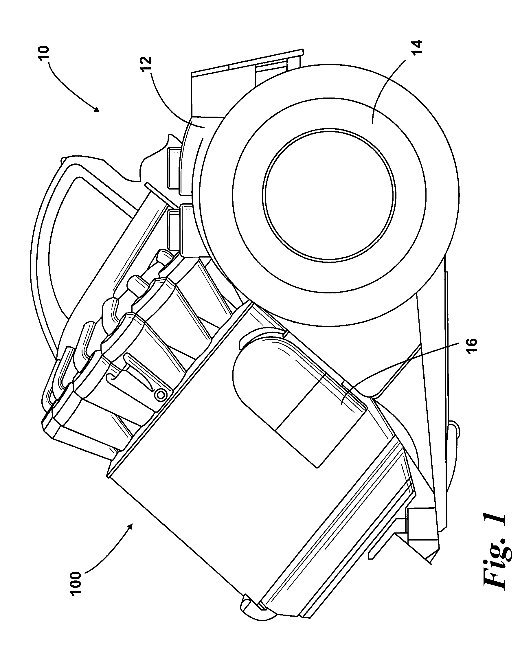
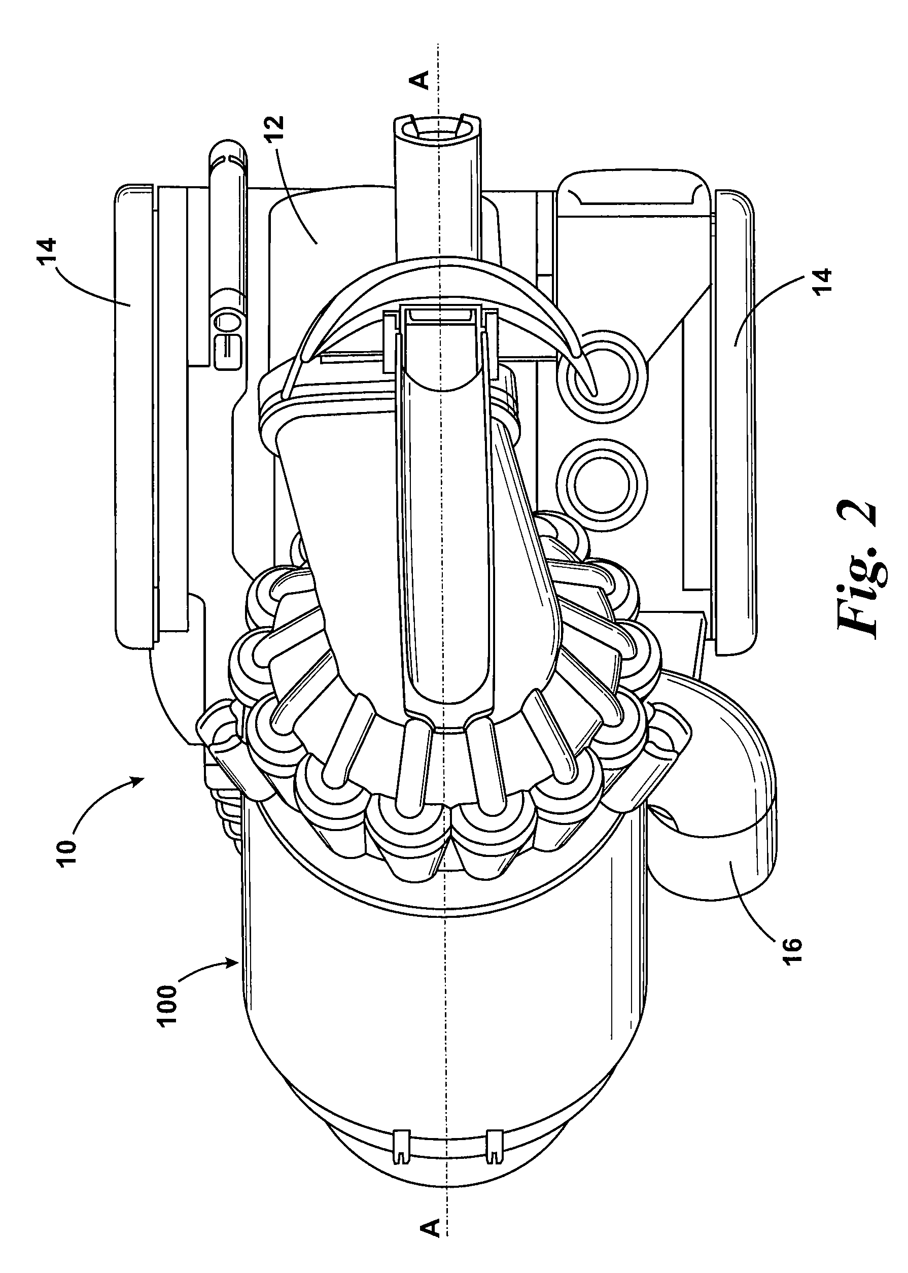
[0024]A cylinder vacuum cleaner 10 incorporating cyclonic separating apparatus according to the invention is shown in FIGS. 1 and 2. The vacuum cleaner 10 has a main body 12 housing a motor and fan unit (not shown) and to which a pair of wheels 14 is attached. The wheels 14 allow the main body 12 of the vacuum cleaner 10 to be maneuvered across a floor surface. A dirty air inlet 16 is formed on the main body 12. A hose and wand assembly (not shown) can be connected to the dirty air inlet 16 in order to enable a user to clean a floor surface.

[0025]Cyclonic separating apparatus 100 according to the invention is releasably attached to the main body 12. The interior of the cyclonic separating apparatus 100 is in communication with the dirty air inlet 16 through which a dirt-laden airflow enters the cyclonic separating apparatus 100. The cyclonic separating apparatus 100 can be removed from the main body 12 for emptying purposes.

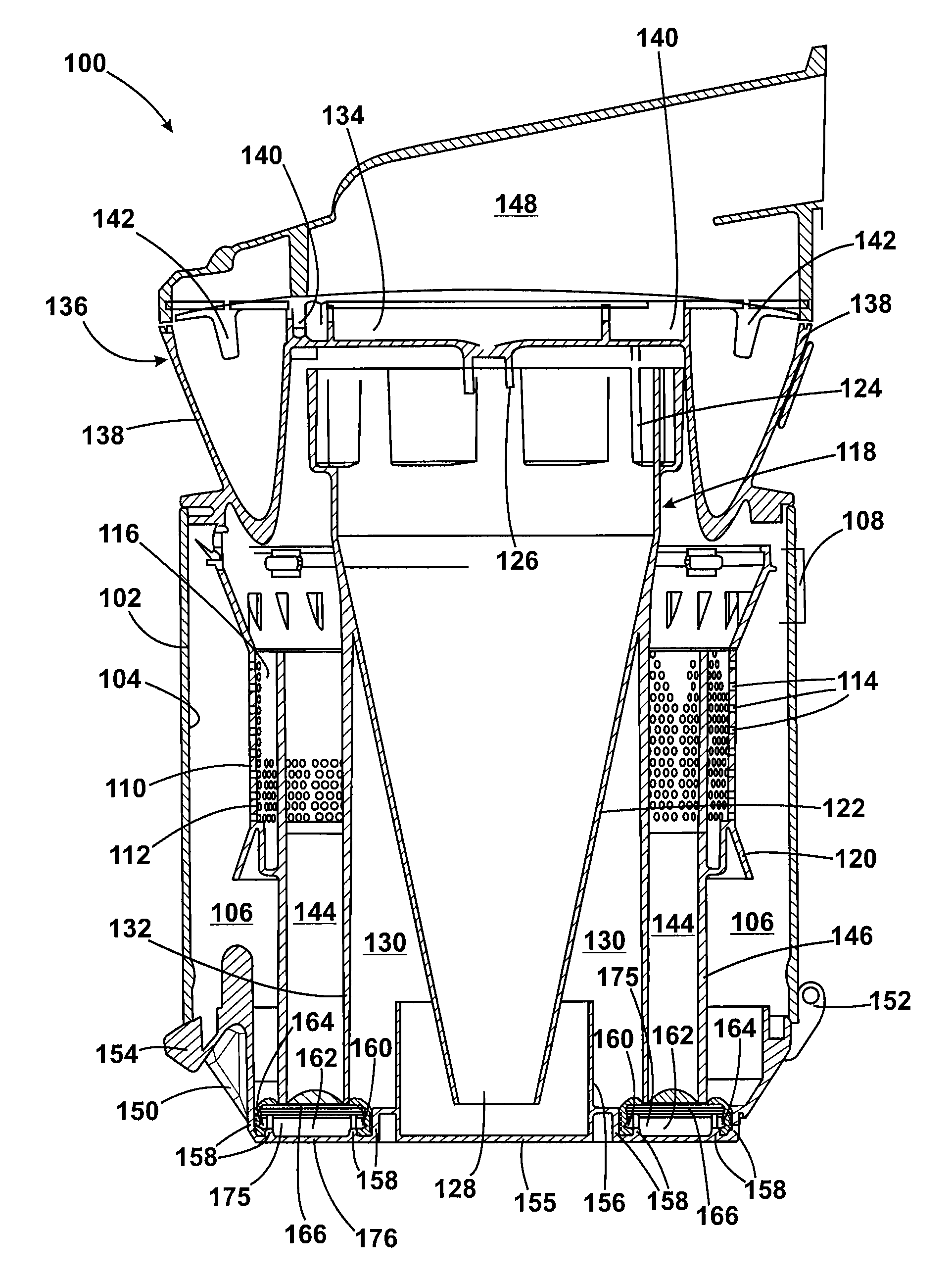
[0026]The cyclonic separating apparatus 100 is shown in mor...


PUM

PropertyMeasurementUnit
brittleaaaaaaaaaa
areaaaaaaaaaaa
flexibleaaaaaaaaaa

Abstract

A cyclonic separating apparatus for a cleaning appliance includes a plurality of cyclonic separators arranged in series for separating particles from a dirt- and dust-laden airflow, at least three collectors for collecting separated dirt and dust, and a closure member movable between a closed position in which the closure member closes an end of each collector and an open position in which separated dirt and dust can be emptied from the collectors. The ends of the collectors are separated by dividing walls. A seal is provided to seal between the closure member and the dividing walls when the closure member is in the closed position. This common seal between the dividing walls and the closure member is able to seal effectively even if the closure member is misaligned or incorrectly fitted.

Description

REFERENCE TO RELATED APPLICATIONS[0001]This application claims the priority of United Kingdom Application No. 0720340.9, filed Oct. 18, 2007, the contents of which are incorporated herein by reference.FIELD OF THE INVENTION[0002]The present invention relates to cyclonic separating apparatus for a cleaning appliance. Particularly, but not exclusively, the present invention relates to cyclonic separating apparatus for a vacuum cleaner.BACKGROUND OF THE INVENTION[0003]Vacuum cleaners which utilise cyclonic separating apparatus are well known. Examples of such vacuum cleaners are shown in EP 0 042 723, EP 1 370 173 and EP 1 268 076. In general, an airflow in which dirt and dust is entrained enters a first cyclonic separator via a tangential inlet which causes the airflow to follow a spiral or helical path within the first cyclonic separator so that the dirt and dust is separated from the airflow. Relatively clean air passes out of the chamber while the separated dirt and dust is collect...

Claims


Application Information

Patent Timeline
Patent Type & Authority Patents(United States)
IPC IPC(8): A47L9/16B01D45/12
CPCA47L9/106A47L9/1625A47L9/1641A47L9/1683A47L9/16A47L9/1608A47L9/1616B04C5/00B04C5/08B04C5/24B04C5/26
Inventor BATES, ADAM JAMESSTICKNEY, TIMOTHY NICHOLAS
Owner DYSON TECH LTD
Why Eureka
Try Eureka