Inkjet recording apparatus

a recording apparatus and a technology of a recording plate, applied in the direction of printing, other printing apparatus, etc., can solve the problems of insufficient suction power to suction the sheet, small air circulation hole rate, and inability to obtain sufficient negative pressure for suctioning the recording medium, so as to prevent the fluctuation of suction power and prevent the recording medium

Active Publication Date: 2013-02-26
KYOCERA DOCUMENT SOLUTIONS INC
View PDF17 Cites 11 Cited by
  • Summary
  • Abstract
  • Description
  • Claims
  • Application Information

AI Technical Summary

Benefits of technology

[0010]An object of the present invention is to provide an inkjet recording apparatus, which is capable of preventing fluctuation of the suction power for suctioning a recording medium, and preventing the recording medium from floating in a region facing a nozzle surface of an inkjet head.

Problems solved by technology

When, on the other hand, the rate of the air circulation holes closed by the sheet is small, such as when the sheet is positioned on an upstream side or downstream side of the inkjet head, the suction power to suction the sheet is not sufficient.
Specifically, in the latter situation, there are a number of unclosed air circulation holes from which a large amount of air is suctioned, and as a result a sufficient negative pressure for suctioning the recording medium cannot be obtained.
In addition, when the suction power to suction the sheet is not sufficient in a region facing the nozzle surface of the inkjet head, the front edge or rear edge of the sheet floats away from the conveying belt and abuts on the inkjet head.

Method used


Image

  • Inkjet recording apparatus
  • Inkjet recording apparatus
  • Inkjet recording apparatus

Examples


Embodiment Construction

[0020]The inkjet recording apparatus according to an embodiment of the present invention is described hereinafter in detail with reference to the drawings.

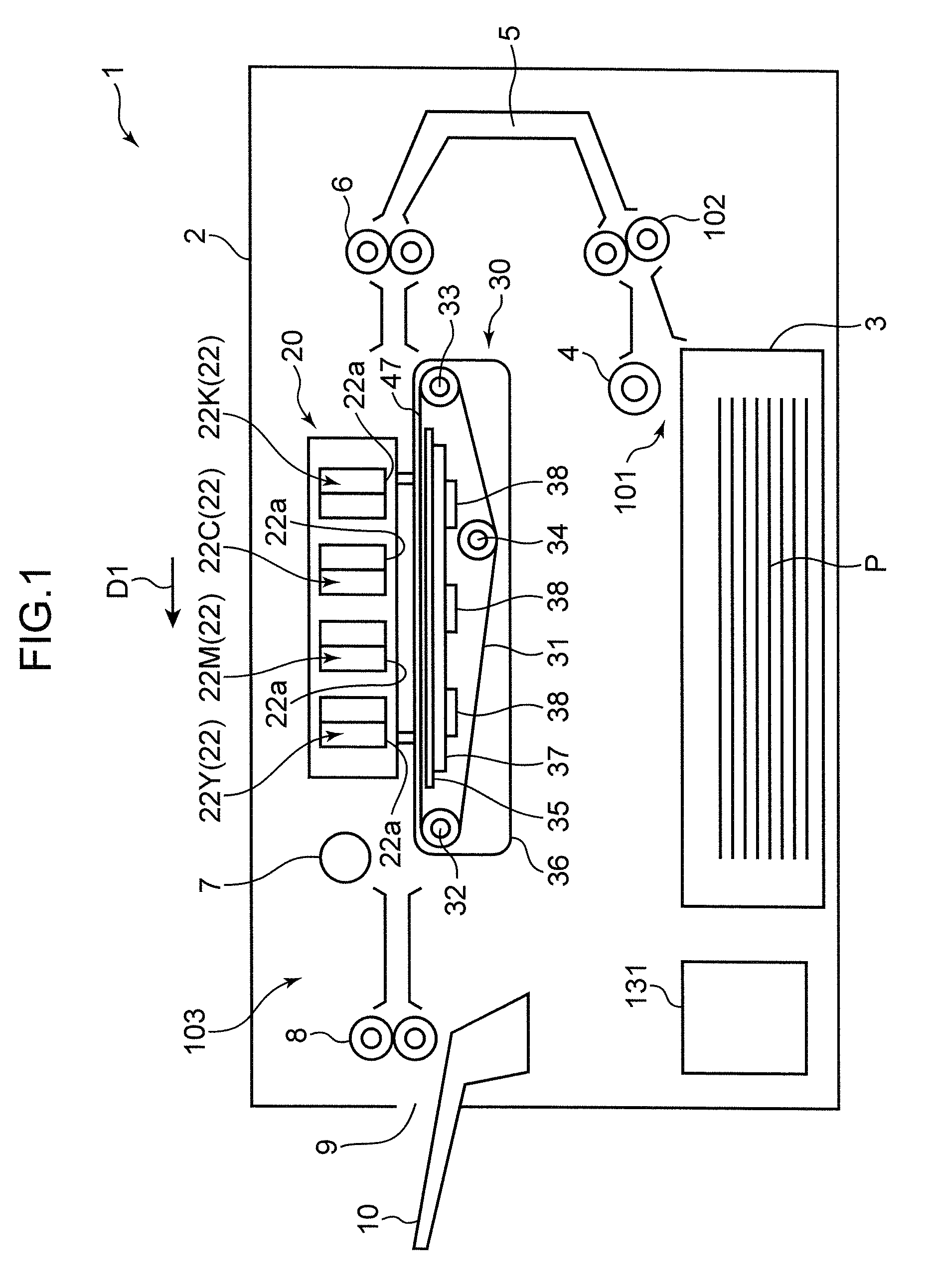
[0021]An inkjet recording apparatus 1 shown in FIG. 1 is an inkjet printer that is capable of forming an image on a recording medium, e.g., a sheet P, on the basis of image information received from an external computer. This recording apparatus 1 has, within a casing 2 thereof, a recording part 20, sheet storing part 101, sheet conveying path 5, conveyance unit 30, delivery part 103, and controller 131 controlling these elements. It should be noted in the following description that a conveying direction in which the sheet P is conveyed on the conveyance unit 30 is referred to as “direction D1” and a direction perpendicular thereto (a width direction of the sheet P) as “direction D2.”

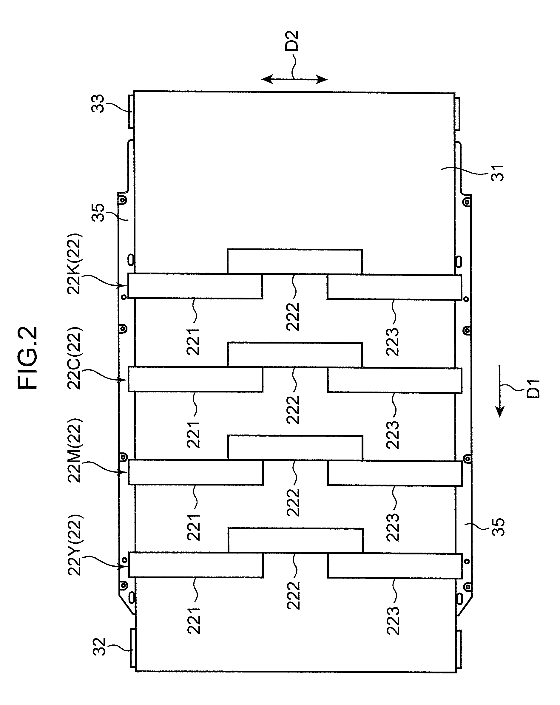
[0022]The recording part 20 has four groups of inkjet heads 22 (22K, 22C, 22M and 22Y) corresponding to colors black, cyan, magenta and yellow, seque...


PUM


Abstract

A conveying platen is provided with a plurality of air circulation parts, each of which includes a long groove opened toward the conveying belt and formed in a longitudinal direction following a conveying direction, and a hole that penetrates in a thickness direction from a part of a bottom surface of the long groove. These air circulation parts are arrayed in the conveying direction and a width direction perpendicular to the conveying direction. The conveying platen has an opposed region which faces a nozzle surface. The long groove is provided in the opposed region. The hole is provided in a region other than the opposed region.

Description

BACKGROUND OF THE INVENTION[0001]1. Field of the Invention[0002]The present invention relates to an inkjet recording apparatus.[0003]2. Description of the Related Art[0004]As an inkjet recording apparatus that has a conveyance mechanism for conveying a recording medium such as a sheet of paper, the following inkjet recording apparatus is known. Examples of the conveyance mechanism include the one that has a conveying belt with a plurality of through-holes and having a sheet mounted on a front surface thereof, a conveying plate that is oppositely disposed along a lower surface of the conveying belt and provided with a plurality of air circulation holes on nearly the entire conveying plate, and negative pressure generating means disposed below the conveying plate and for suctioning the sheet through the air circulation holes of the conveying plate and the through-holes of the conveying belt. In an inkjet, a nozzle surface provided with a plurality of nozzles is disposed opposite to th...

Claims


Application Information

Patent Timeline
Patent Type & Authority Patents(United States)
IPC IPC(8): B41J2/01
CPCB41J2/155B41J11/0085
Inventor IKEDA, MASAMI
Owner KYOCERA DOCUMENT SOLUTIONS INC
Why Eureka
Try Eureka