Slurry flow control device
a flow control and slurry technology, applied in the direction of diaphragm valves, engine diaphragms, functional valve types, etc., can solve the problems of unsatisfactory conditions and continued slurry flow
- Summary
- Abstract
- Description
- Claims
- Application Information
AI Technical Summary
Benefits of technology
Problems solved by technology
Method used
Image
Examples
Embodiment Construction
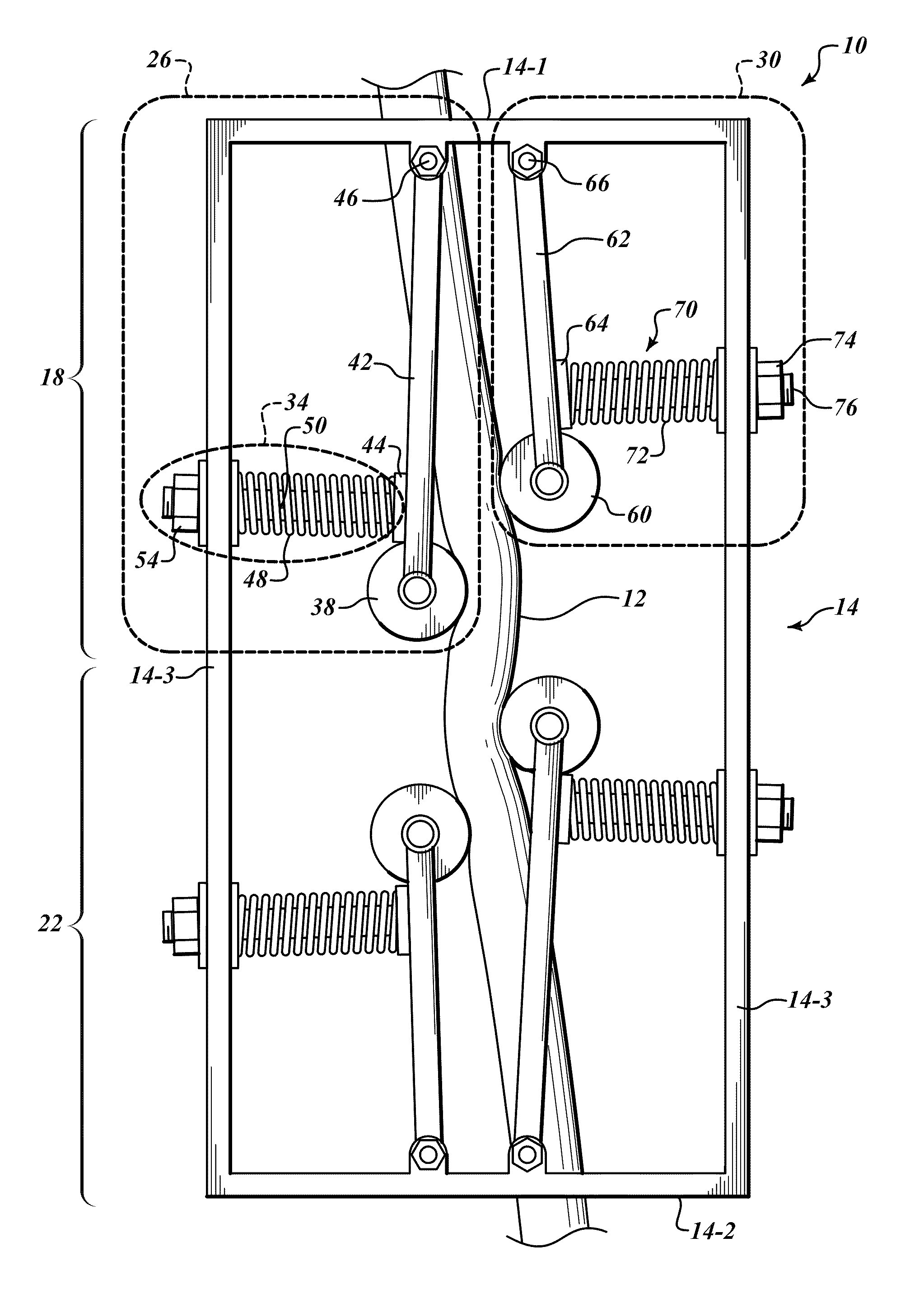
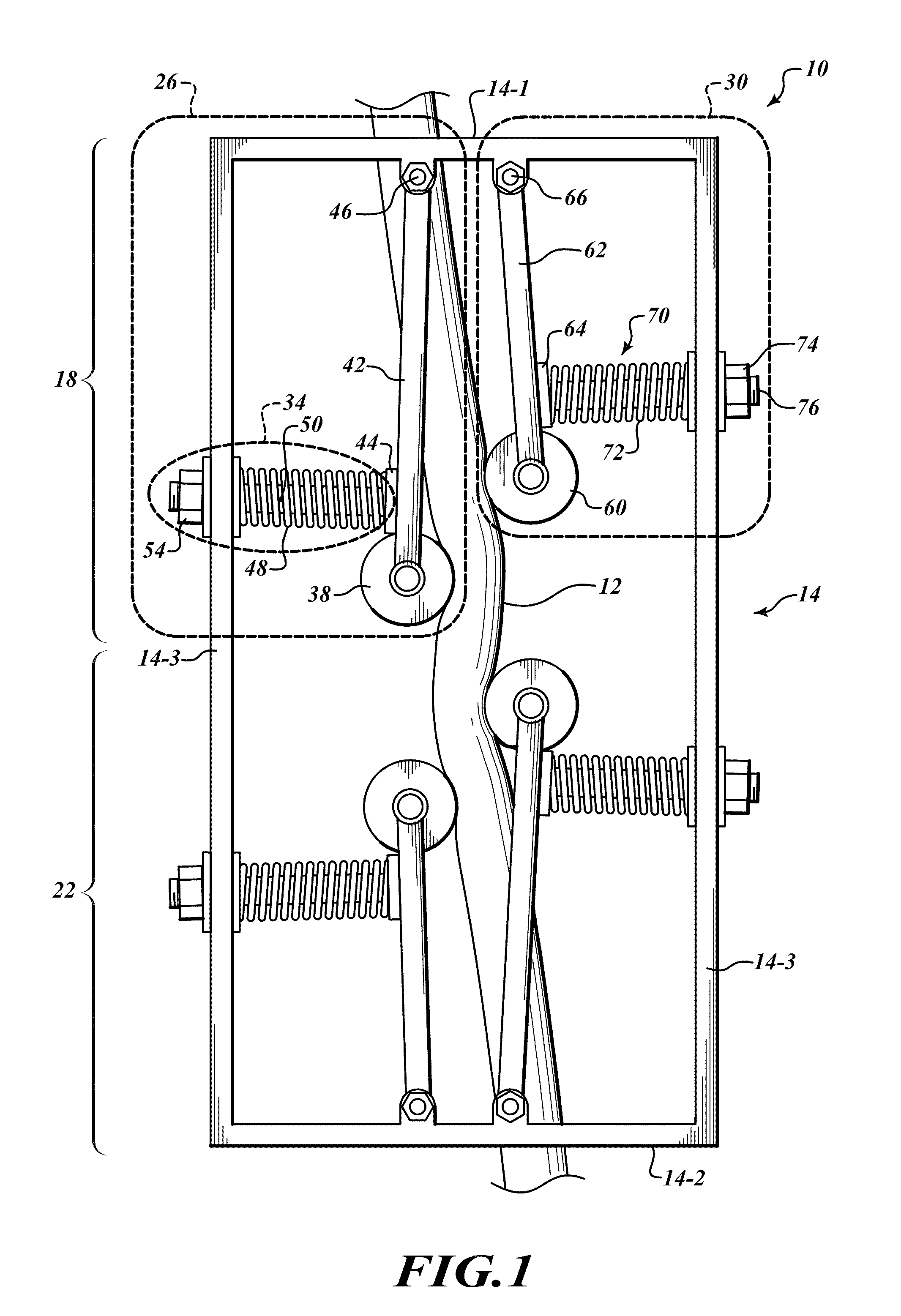
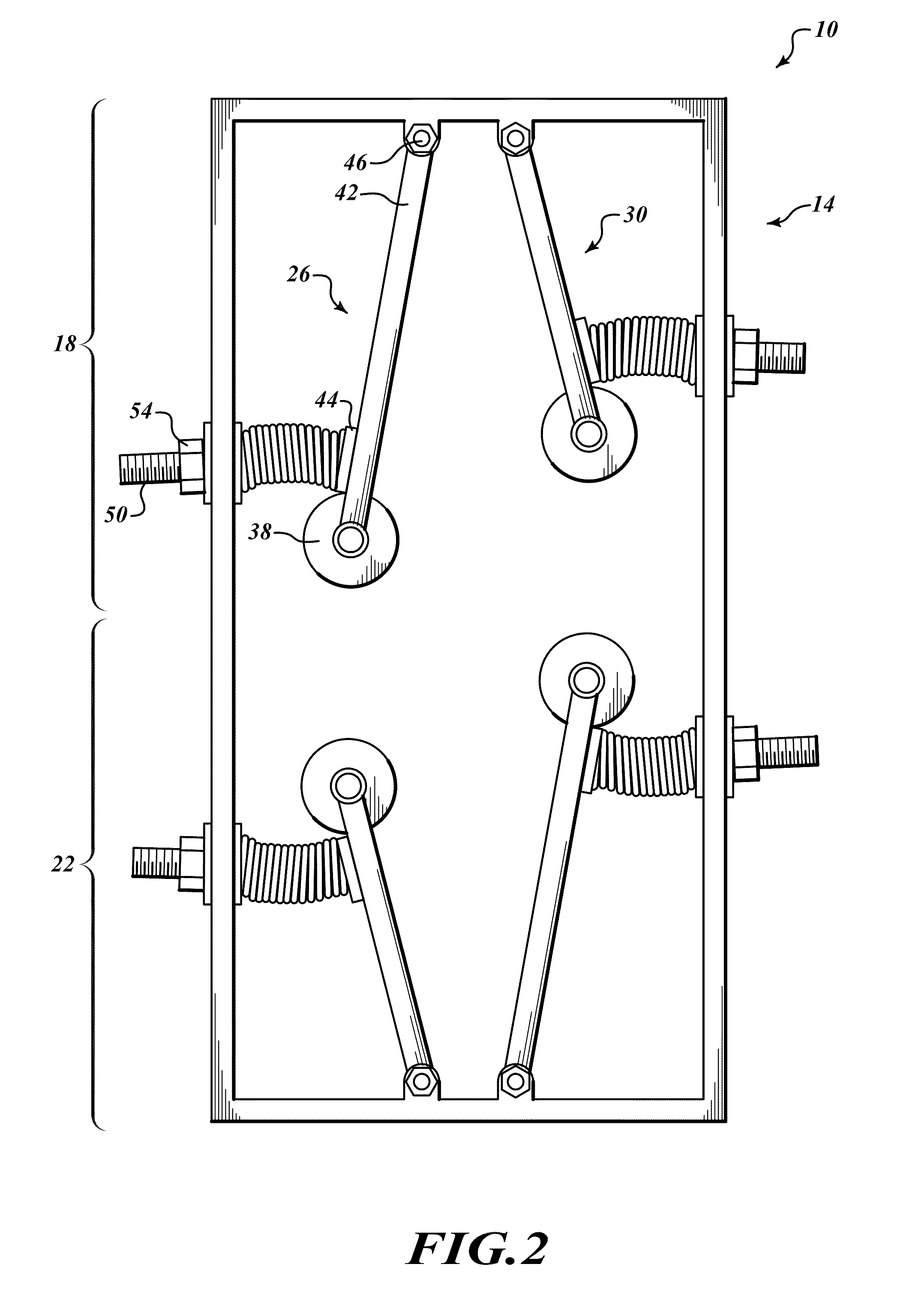
[0009]FIGS. 1-3 illustrate an embodiment of an example slurry flow control device 10 designed to control flow of an applied slurry (such as concrete) through a flexible-walled transport tube 12. The slurry control device 10 includes a frame 14, a first flow restrictor 18 and a second flow restrictor 22. Each flow restrictor includes first and second swing arm components 26, 30, respectively.
[0010]In one embodiment, the frame 14 is an elongated box-like structure that includes top segments 14-1, bottom segments 14-2 and four vertical segments 14-3. The four vertical segments 14-3 connect the top segments 14-1 to the bottom segments 14-2. The first flow restrictor 18 is located in an upper half of the frame 14 and the second flow restrictor 22 is located in a lower half of the frame 14. The flexible-walled transport tube 12 passes through each of the first and second flow restrictors 18, 22, and through the top and bottom frame segments 14-1, 14-2.
[0011]The swing arm component 26 incl...
PUM
 Abstract
Description
Claims
Application Information
 - R&D
- Intellectual Property
- Life Sciences
- Materials
- Tech Scout
- Unparalleled Data Quality
- Higher Quality Content
- 60% Fewer Hallucinations
Browse by: Latest US Patents, China's latest patents, Technical Efficacy Thesaurus, Application Domain, Technology Topic, Popular Technical Reports.
© 2025 PatSnap. All rights reserved.Legal|Privacy policy|Modern Slavery Act Transparency Statement|Sitemap|About US| Contact US: help@patsnap.com


