Drive wheel suspension

a technology of suspension and drive wheel, which is applied in the direction of axle suspension, propulsion parts, cycle equipment, etc., and can solve problems such as affecting performan

Inactive Publication Date: 2013-03-19
LENDER COLLECTIONS
View PDF11 Cites 15 Cited by
  • Summary
  • Abstract
  • Description
  • Claims
  • Application Information

AI Technical Summary

Problems solved by technology

However because of the functionality and practical appeal of the vehicles, the same are being used in environments not having a particularly smooth operating surface, such as by way of example, poorly maintained parking lots and the like where rigid mounting of the vehicle substantially affects performance.

Method used


Image

  • Drive wheel suspension
  • Drive wheel suspension
  • Drive wheel suspension

Examples


Embodiment Construction

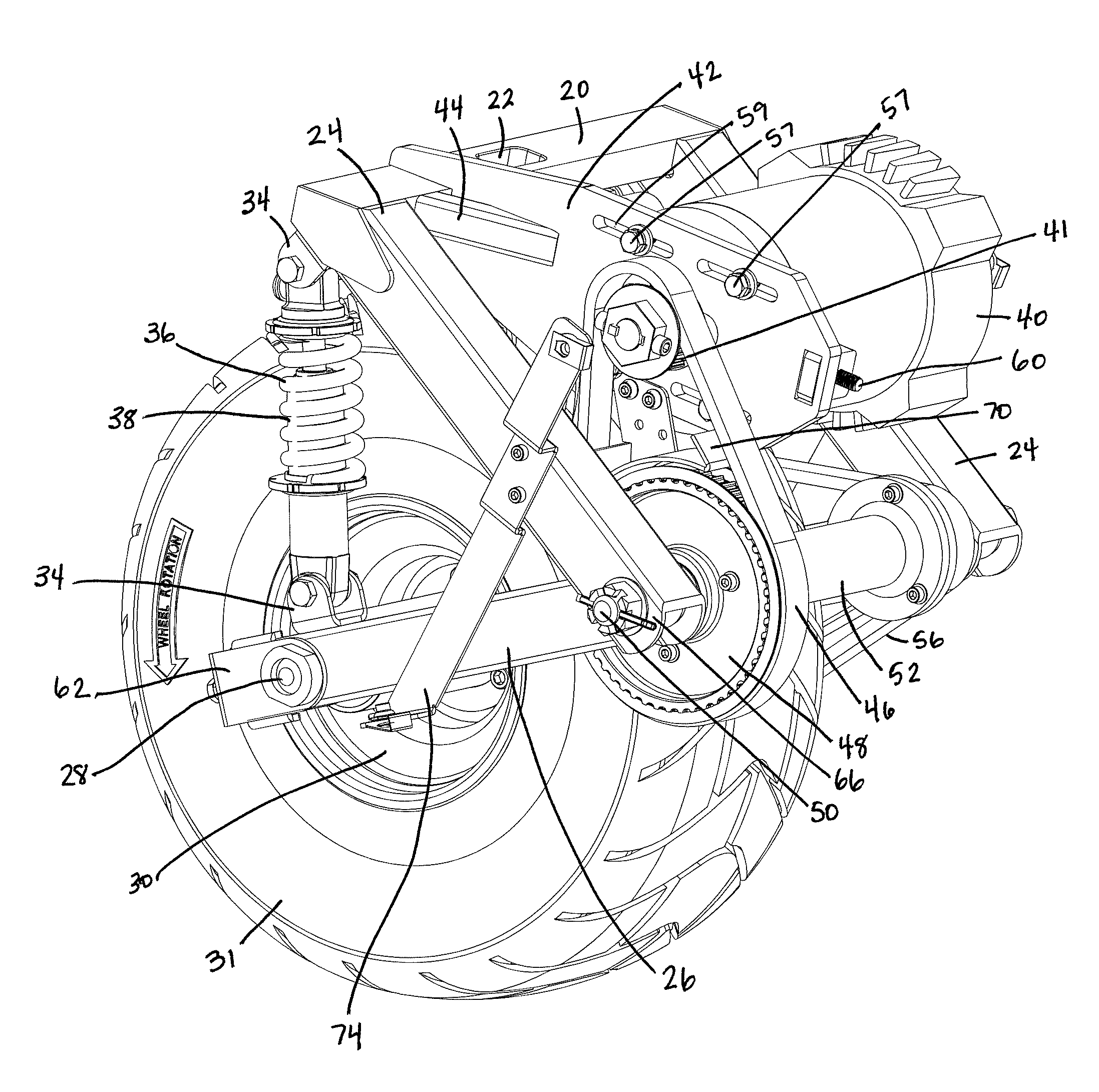
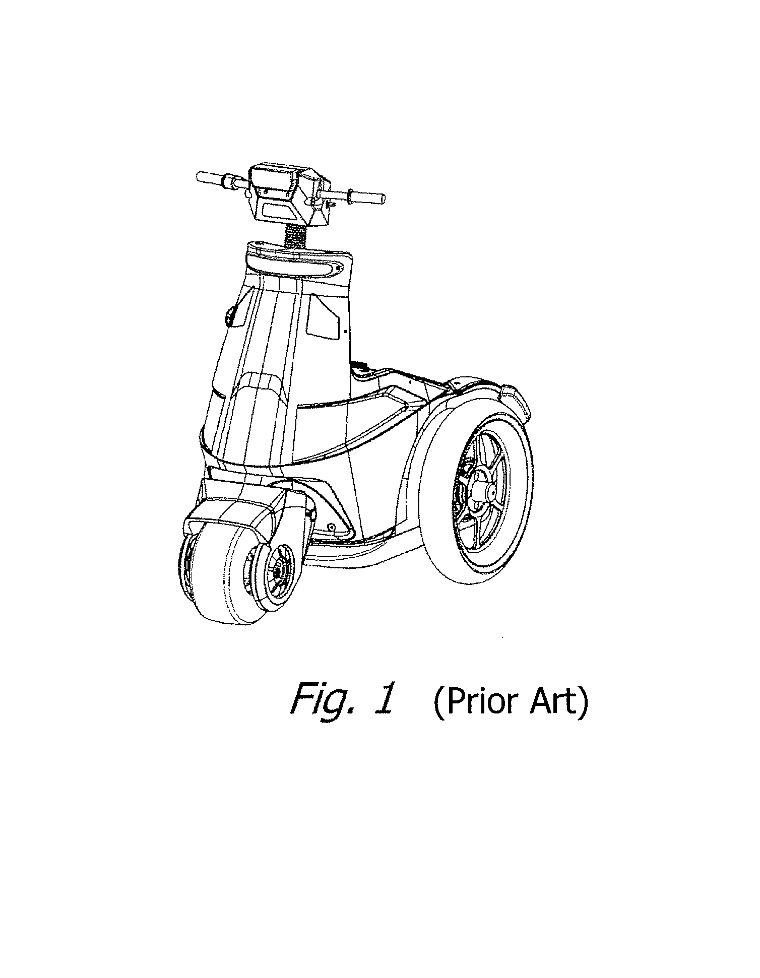
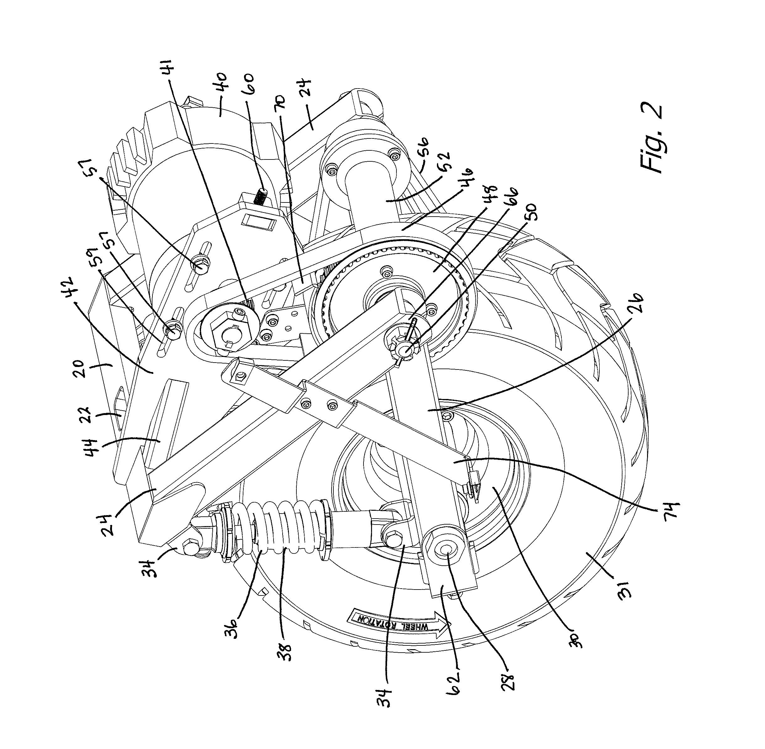
[0010]The present invention comprises a spring mounted drive wheel for an electric powered vehicle such as that shown in FIG. 1. FIG. 2 is a first side perspective view of the suspension and drive, FIG. 3 is an opposite side perspective view of the suspension and drive system, and FIG. 4 is a front view thereof. A main crossbar 20 has a socket-like opening 22 therein to which a steering post will be fastened. Welded to the main crossbar 20 are a pair of downward and rearward projecting struts 24 which provide support for swing arms 26, which support the axle 28, which in turn supports wheel 30 on bearings (not shown) of conventional design. Between the upper ends of struts 24 and the forward part of swing arms 26, just above axle 28, are clips 34 which support coil springs 36, each having a shock absorber 38 therein. The springs are generally chosen to support the weight applied to that wheel, with the swing arms 26 in a substantially level or horizontal position, as may be seen in ...


PUM


Abstract

A drive wheel and suspension for a vehicle for mounting on a steering post to provide both a steering capability and propulsion to the vehicle. The drive wheel and suspension provides a spring suspension for that wheel of the vehicle, as well as what is effectively vehicle body mounting of the propulsion system so as to minimize un-sprung weight and to provide a compact assembly to support a suitable aesthetic and protective fender over the drive wheel and suspension.

Description

BACKGROUND OF THE INVENTION[0001]1. Field of the Invention[0002]The present invention relates to the field of drive wheel suspension for vehicles.[0003]2. Prior Art[0004]T3 Motion, Inc., assignee of the present invention, now manufactures and sells the three-wheeled battery operated vehicle shown in FIG. 1. The vehicle is operated standing up, with all of the controls necessary being accessible on the handlebars. The vehicle has found wide application for security purposes, as it typically can operate all day in a typical application on a single charge, both indoors such as in shopping centers and outdoors for policing such areas as parking lots, parking structures, beach areas and the like. The vehicle has found wide use for such purposes not only because of its efficiency (cost of operation), but also because the operator is elevated somewhat, so can see over people for a better view of the area.[0005]In the prior art vehicles as shown in FIG. 1, the wheels are rigidly mounted, th...

Claims


Application Information

Patent Timeline
Patent Type & Authority Patents(United States)
IPC IPC(8): B62D61/06B62K5/02
CPCB62K25/283B62K2204/00
Inventor NAM, KI Y.TARAS, RICHARDPHAM, HUNG
Owner LENDER COLLECTIONS
Why Eureka
Try Eureka