Method of network reconfiguration in optical transport networks

a network reconfiguration and optical transport technology, applied in the field of optical communication network management, can solve the problems that the procedures for other types of network reconfiguration have not yet been developed

Active Publication Date: 2013-03-19
CIENA
View PDF4 Cites 22 Cited by
  • Summary
  • Abstract
  • Description
  • Claims
  • Application Information

AI Technical Summary

Problems solved by technology

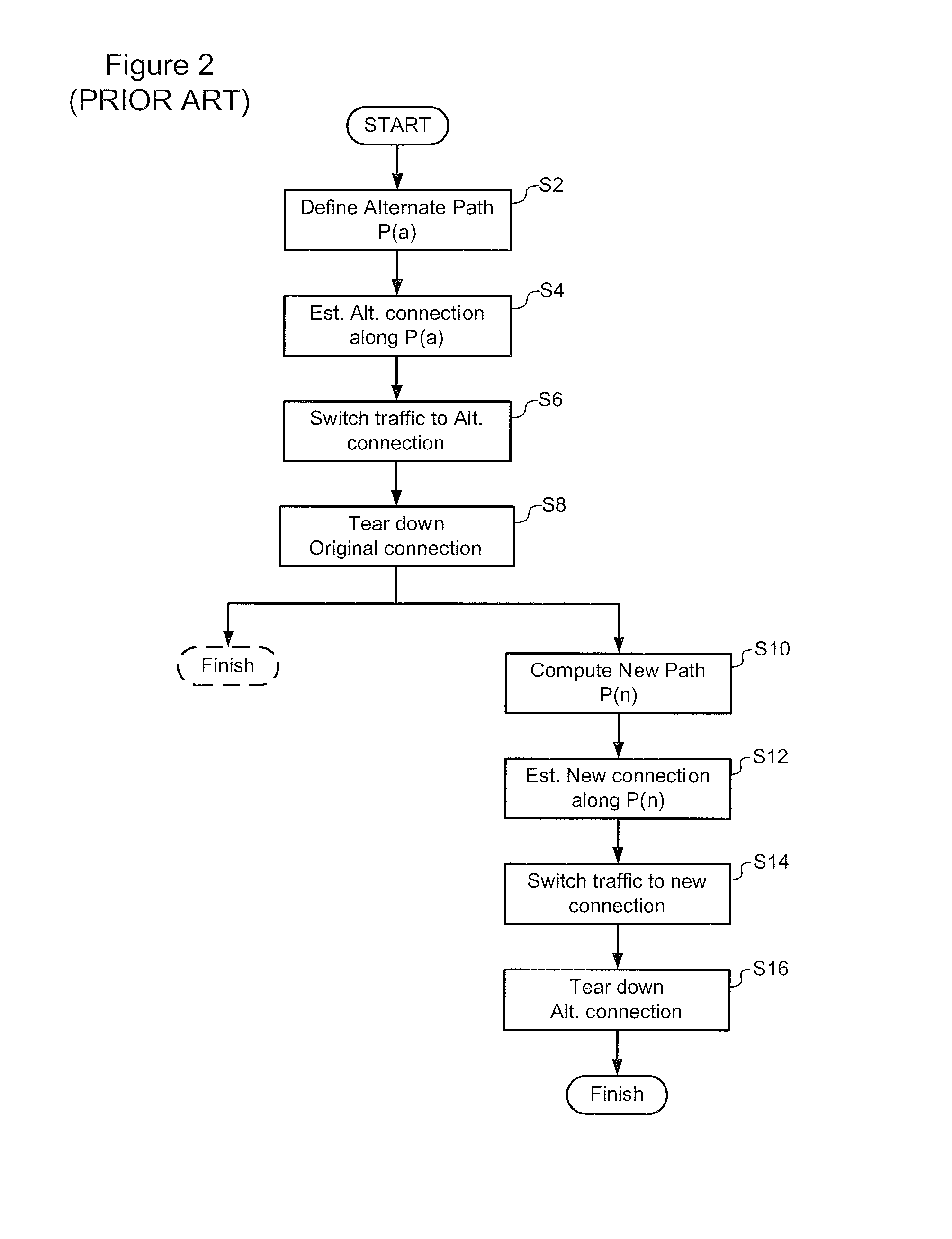
Apart from the addition or deletion of individual nodes as described above, procedures for other types of network reconfigurations have not been yet been developed.

Method used


Image

  • Method of network reconfiguration in optical transport networks
  • Method of network reconfiguration in optical transport networks
  • Method of network reconfiguration in optical transport networks

Examples


Embodiment Construction

[0027]The present invention provides techniques for in-service network reconfigurations involving changes in the Control Plane Name Space.

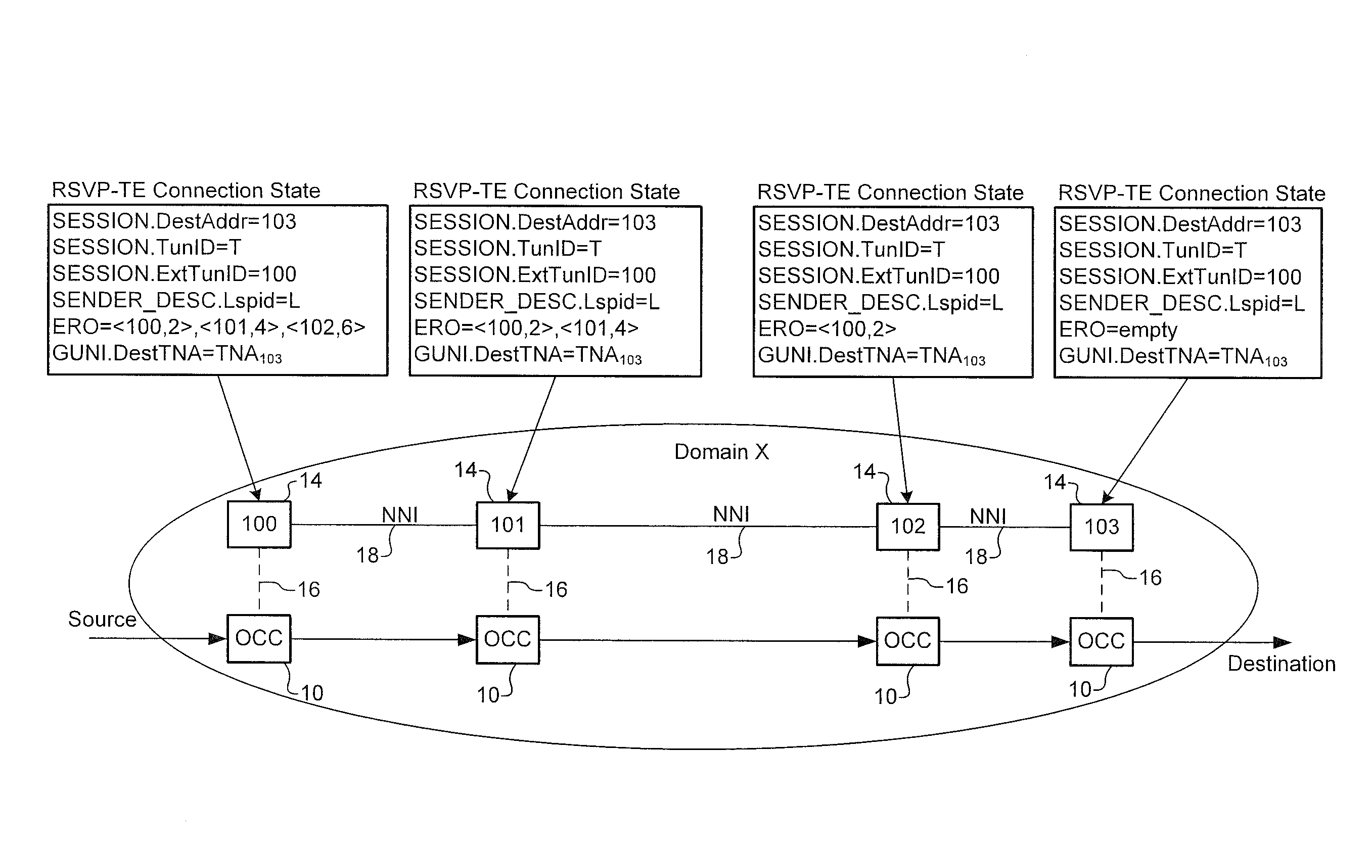
[0028]In very general terms, network reconfiguration processes in accordance with the present invention utilize a pair of name spaces in the Control Plane, and implement CP-to-MP and MP-to-CP migrations. FIG. 3A is a flow-chart illustrating a representative network reconfiguration process in accordance with the present invention.

[0029]In the example of FIG. 3A, it is assumed that the network is operating with a first version of the Control Plane Name Space (referred to as CPNS-v1). At a first step (at S18), a CP-to-MP migration is executed to remove existing Control Plane connection state (defined under the original CPNS-v1) and transfer ownership of all the corresponding Transport Plane connections to the Management Plane 8. In some embodiments, this CP-to-MP migration may follow a standard migration process, such as, for example, as defined unde...


PUM


Abstract

A method of reconfiguring a network having a transport plane for carrying subscriber traffic flows within end-to-end connections, a control plane for managing at least a portion of resources of the transport plane allocated to each connection, and a management plane for implementing management functions in the control plane and any resources of the transport plane that are not managed by the control plane. The method comprises installing an updated version of a control plane name space for a target node of the network. For each connection traversing the target node: a control plane to management plane migration is performed for removing connection state in the control plane associated with the connection, so as to transfer ownership of the connection from the control plane to the management plane; followed by a management plane to control plane migration for installing new connection state in the control plane associated with the connection, so as to transfer ownership of the connection from the management plant to the control plane, the new connection state being defined using the updated version of the control plane name space.

Description

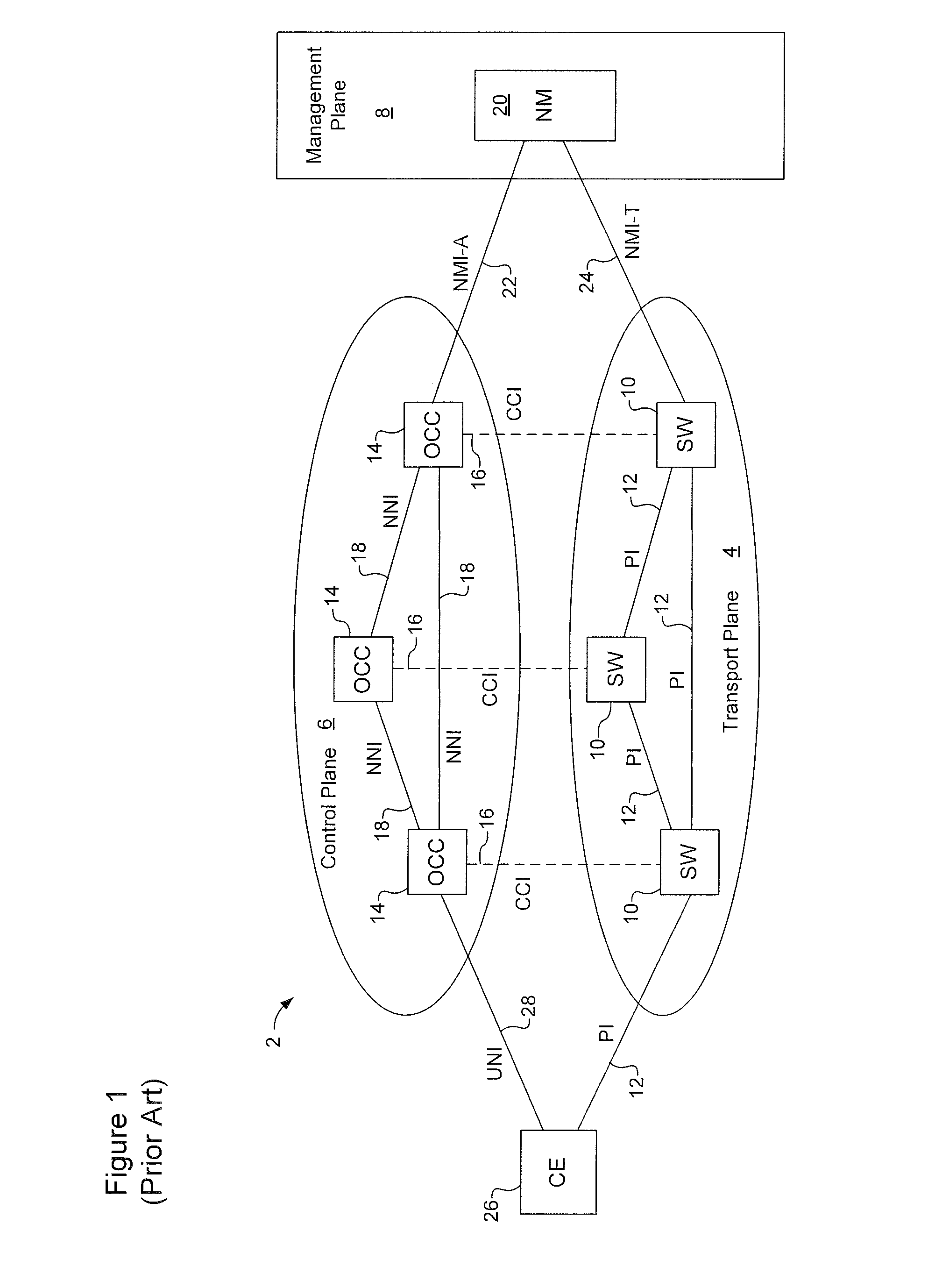
CROSS-REFERENCE TO RELATED APPLICATIONS[0001]This is the first application filed in respect of the present invention.FIELD OF THE INVENTION[0002]The present application relates generally to management of optical communications networks, and more specifically, to methods of network reconfiguration in optical transport networks.BACKGROUND OF THE INVENTION[0003]FIG. 1 schematically illustrates the logical structure of an optical transport network in accordance with ITU-T recommendation G.8080 / Y.1304, entitled Architecture for the Automatically Switched Optical Network (ASON), the entire content of which is incorporated herein by reference. As may be seen in FIG. 1, the network 2 is logically divided into a transport plane 4, a control plane 6 and a management plane 8.[0004]The Transport Plane 4 comprises a plurality of switches 10 interconnected by Physical Interfaces (PIs) 12, and is responsible for transporting user data via end-to-end connections provisioned through the network. The...

Claims


Application Information

Patent Timeline
Patent Type & Authority Patents(United States)
IPC IPC(8): G06F15/177
CPCH04L41/0896
Inventor SKALECKI, DAREKSWINKELS, GERARD L.ROCH, EVELYNE
Owner CIENA
Why Eureka
Try Eureka