Self-inking hand stamp

a self-inking, hand stamp technology, applied in the field of self-inking hand stamps, can solve the problems of affecting the canting or self-locking of the actuating bow on the housing of the hand stamp, and affecting the strength and stability of the latter

Active Publication Date: 2013-03-26
COLOP STEMPELERZEUGUNG SKOPEK GMBH & CO KG
View PDF22 Cites 14 Cited by
  • Summary
  • Abstract
  • Description
  • Claims
  • Application Information

AI Technical Summary

Benefits of technology

[0007]It is now an object of the invention to provide a self-inking hand stamp of the type as mentioned above which allows for a simple, yet reliable attachment of an ink pad holder in the upper region of the metal frame of the hand stamp, wherein, moreover, the expenditures for the production and mounting shall be kept low.
[0010]In any event, for mounting the carrying members, it is advantageous if they have latching projections by means of which they may be simply fixed in associated latching openings of the frame side walls by snapping engagement. For a good positioning and a high position stability it is, furthermore, suitable if the resting projections are provided above the latching projections. By the fact that in that case always two projections are provided one above the other, which projections extend through separate openings (or which project through a common, slot-shaped, elongate opening), rotation of the respective carrying member is effectively counteracted. In a simple embodiment, however, it is also conceivable that the latching projections themselves constitute the resting projections. In this case, the projections suitably have a non-round, e.g. a rectangular, cross-section so as to counteract a rotation in the latching opening.
[0012]For a particularly good positioning and fixation of the carrying and guiding members in their positions, respectively, it is, furthermore, advantageous if each carrying member has an upper, flange-like roof projection which abuts on an upper transition region joining the side wall to the upper cover wall of the frame.
[0015]With a view to the desired fixing by latching engagement as well as, optionally, the advantageous sliding guiding of the bow legs it is, as has been mentioned, particularly advantageous if the carrying members are made of plastics, such as POM, ABS or PE, e.g. In this case, if necessary or desired, during insertion of an ink pad holder, the resting projections may be slightly downwardly deflected under elastic deformation to thereby allow for insertion of the ink pad holder without any problems as well as retention of the ink pad holder by elastic, frictional abutment on the latter.

Problems solved by technology

However, neither this axle guide nor the telescopic tube are intended as the guide proper for the actuating bow on the frame, much rather these components a priori have other functions and, therefore, malfunctions to the point of canting or self-locking of the actuating bow on the housing of the hand stamp may very well occur.
These hood-shaped guiding parts cause, however, substantial expenditures when producing and assembling the hand stamp.
Moreover, the large opening in the cover wall of the frame negatively affects the strength and stability of the latter.
Such inwardly riveted angle brackets may, however, cause restrictions in terms of dimensioning and movability of the type unit during turning and downward and upward movements thereof, apart from the fact that the attachment of angle brackets in the inner space of the stamp frame is comparatively cumbersome.
If the resting projections are formed by legs which have been punched out and bent, an exact production will be necessary since otherwise the ink pad holder will either knock against the bent lugs and thereby obviate its proper insertion in the frame, or the fit for the ink pad holder in the upper region of the frame will only be a loose one so that the ink pad holder may unintentionally fall out of the hand stamp.
Therefore, time and again, in practice, with the bent-out lugs, comparatively complicated readjustments are necessary.

Method used


Image

  • Self-inking hand stamp
  • Self-inking hand stamp
  • Self-inking hand stamp

Examples


Embodiment Construction

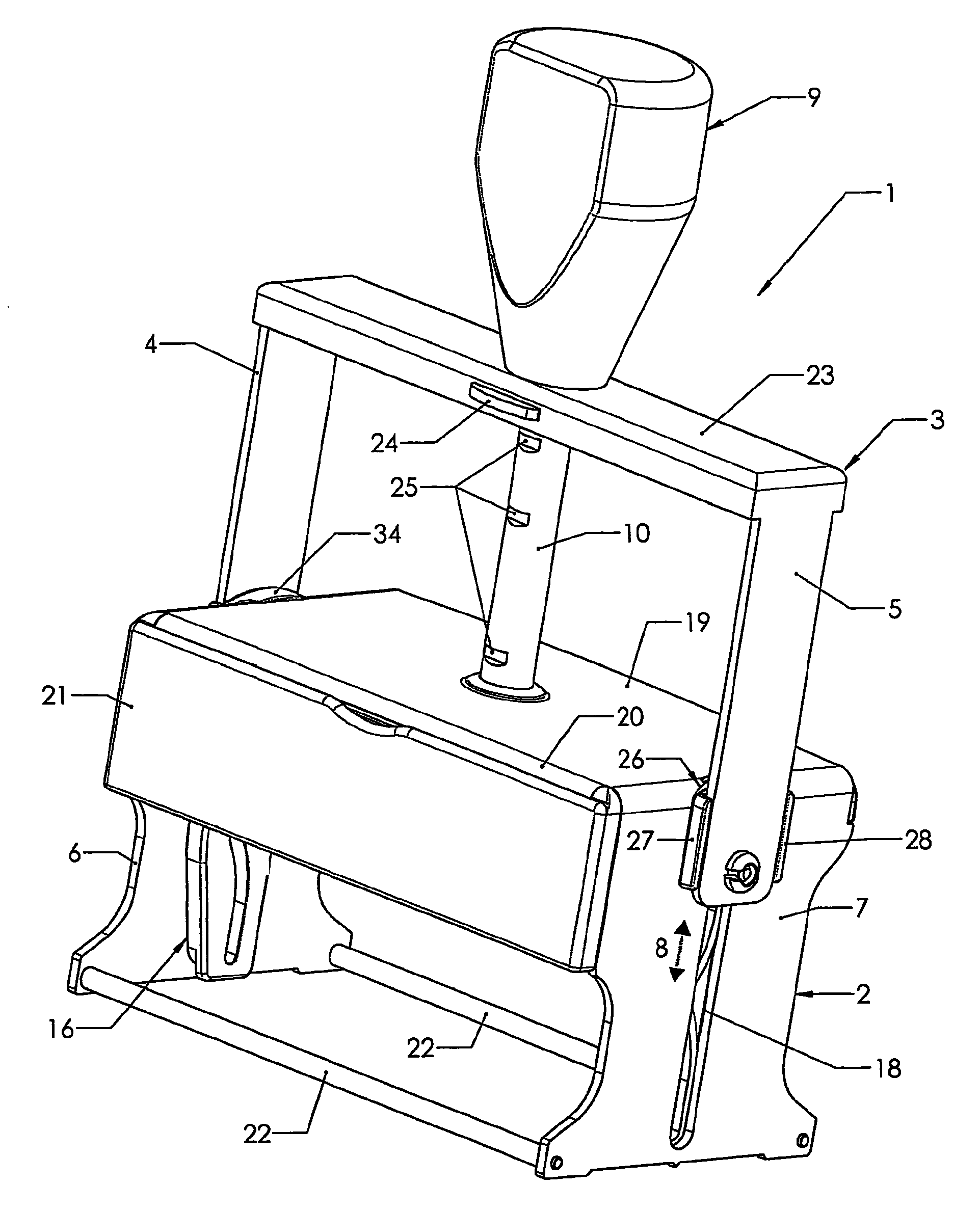
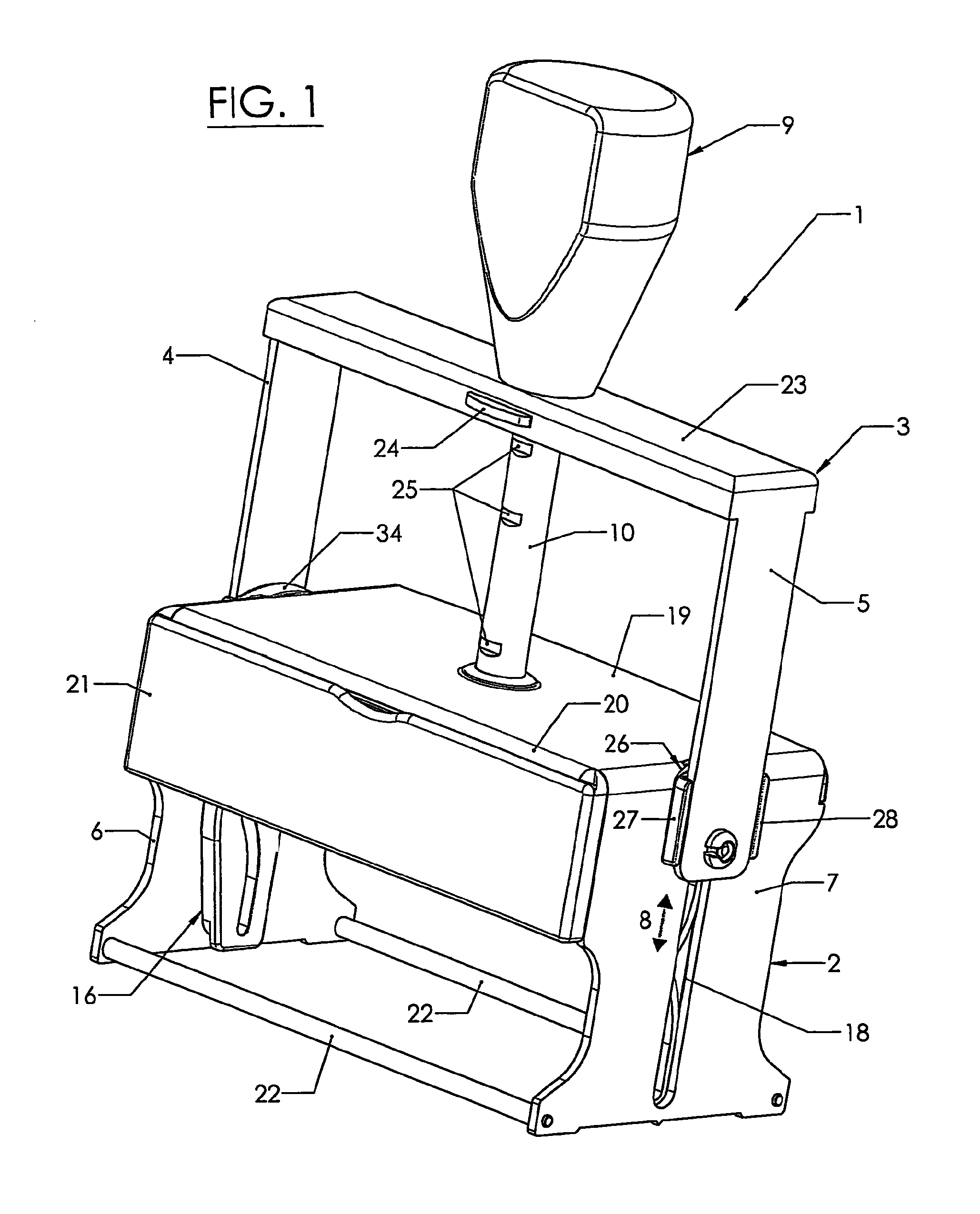
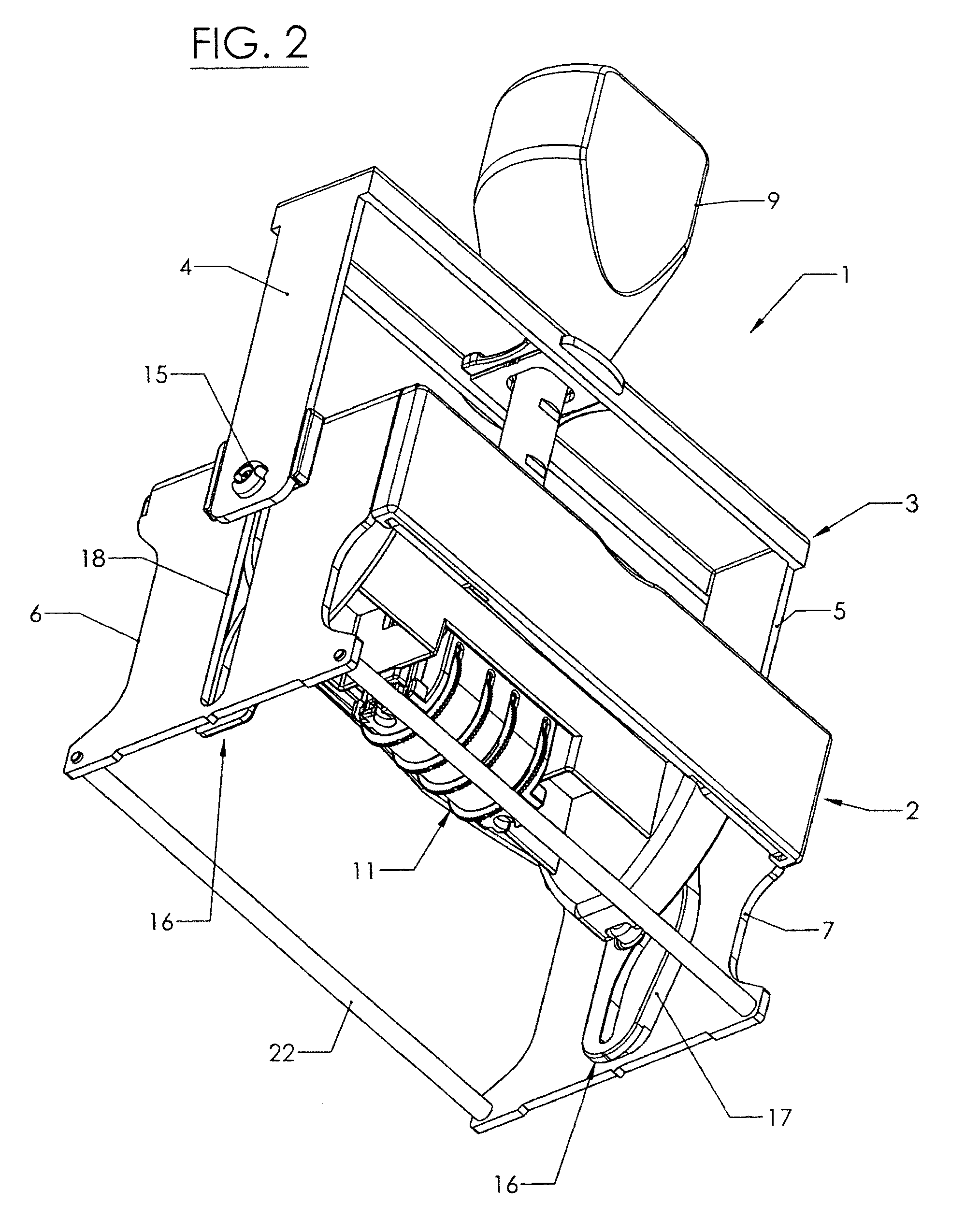
[0023]In FIGS. 1 to 6, a hand stamp 1 with a self-inking mechanism, called self-inking hand stamp 1 in short, is illustrated, which includes a frame or a housing 2 made of metal as well as an actuating bow 3 which is U-shaped in elevation, and is also made of metal. The actuating bow 3 has two legs 4, 5 which are guided on the outer sides of side walls 6, 7 of the metal frame 2 in the operating position so as to be vertically upwardly and downwardly movable, cf. also arrow 8 in FIG. 1. On the upper side of the actuating bow 3, a common handle 9 is attached which, on its inner side, is at least partially hollow so that, in a usual manner, a tube socket 10 can be accommodated in the interior of the handle 9, which tube socket is fixedly attached to the frame 2 on the upper side thereof and serves to receive a helical compression spring (not shown), as is known per se, which spring is supported on the upper side of the frame 2, on the one hand, and in the interior of the handle 9, on t...


PUM


Abstract

A self-inking hand stamp comprising a frame made of metal and having two side walls which are interconnected by an upper cover wall, and further comprising an actuating bow made of metal which, when used, is downwardly movable relative to the frame against a spring force. The actuating bow has two legs which are displaceable along the side walls of the frame; said legs are coupled to a type unit that is displaceable and turnable within the frame; resting projections are provided in the upper region of the frame for an insertable ink pad holder, said resting projections protruding inwards from the inner side of the side walls of the frame; the resting projections are provided on carrying members provided on the outer sides of the side walls and extend through openings in the side walls.

Description

CROSS REFERENCE TO RELATED APPLICATIONS[0001]Applicant claims priority under 35 U.S.C. §119 of Austrian Application No. A 596 / 2009 filed Apr. 17, 2009.FIELD OF THE INVENTION[0002]The invention relates to a self-inking hand stamp comprising a frame made of metal and having two side walls which are interconnected by an upper cover wall, and further comprising an actuating bow made of metal which, when used, is downwardly movable relative to the frame against a spring force, the actuating bow having two legs which are displaceable along the side walls of the frame, said legs being coupled with a type unit that is displaceable and turnable within the frame, resting projections being provided in the upper region of the frame for an insertable ink pad holder, said resting projections protruding inwards from the inner side of the side walls of the frame.BACKGROUND OF THE INVENTION[0003]Such so-called (full) metal self-inking hand stamps have been known for a long time, cf. U.S. Pat. No. 45...

Claims


Application Information

Patent Timeline
Patent Type & Authority Patents(United States)
IPC IPC(8): B41K1/42
CPCB41K1/40B41K1/54B41K1/52
Inventor FABER, ERNST
Owner COLOP STEMPELERZEUGUNG SKOPEK GMBH & CO KG
Why Eureka
Try Eureka