Battery system

a battery system and battery technology, applied in the field of battery systems, can solve the problems of difficult uniform cooling of all battery cells to minimize temperature differences, easy over-charge shorten the life of batteries with high remaining capacity, so as to reduce the temperature differences of battery cells, reduce the cost of battery cells, and reduce the cost of batteries

Inactive Publication Date: 2010-11-25
SANYO ELECTRIC CO LTD
View PDF5 Cites 59 Cited by
  • Summary
  • Abstract
  • Description
  • Claims
  • Application Information

AI Technical Summary

Benefits of technology

[0018]In the battery system of the present invention, temperature equalizing plates 15, 45 can be attached in a layered arrangement on the connecting bands 11, 31. This battery system has the characteristic that battery cell temperature differences can be reduced with an extremely simple structure by disposing temperature equalizing plates in a layered configuration on the connecting bands.
[0019]In the battery system of the present invention, the temperature equalizing plates 35 can be integrated in single-piece configuration with the connecting bands 31. In this battery system, since the shape of the connecting bands is changed to establish the temperature equalizing plates, battery cell temperature differences can be reduced by the connecting bands. Consequently, battery cell temperature differences can be reduced with an extremely simple structure and without the effort of attaching temperature equalizing plates. Further, since temperature equalizing plates are implemented by connecting bands robustly attached to the battery blocks, battery cell temperature differences can be reduced over a long period without any position shift in the temperature equalizing plates.
[0020]In the battery system of the present invention, the surface area opened by the mass-flow regulating openings 16, 46, 36 of the temperature equalizing plates 15, 45, 35 can be smaller at the upstream end than at the downstream end. This battery system can reduce battery cell temperature differences with temperature equalizing plates having a simple shape.
[0021]In the battery system of the present invention, the vertical width of the mass-flow regulating openings 16, 46, 36 of the temperature equalizing plates 15, 45, 35 can be narrower at the upstream end than at the downstream end to reduce the surface area opened at the upstream end. This battery system can reduce battery cell temperature differences by limiting cooling gas flow into the cooling gaps of upstream battery cells with temperature equalizing plates having a simple shape.
[0022]In the battery system of the present invention, connecting bands 11, 31 can be disposed at the top and bottom of the battery stacks 8. In this battery system, cooling gas can flow smoothly into the cooling gaps for efficient cooling while disposing connecting bands on both sides of the battery stacks.
[0023]In the battery system of the present invention, a connecting band 11, 31 can have an upper band 11A, 31A and a lower band 11B, 31B disposed at the top and bottom of a battery stack 8 that are joined together at both ends, and the joined regions 11C, 31C at both ends can be attached to the endplates 10. Since the upper and lower bands of this battery system are joined together, the connecting bands can easily be attached to the endplates. In particular, in a configuration that attaches the connecting bands to the endplates via set screws, this battery system has the characteristic that rotation of the connecting bands can be prevented during set screw tightening allowing simple, reliable attachment to the endplates.

Problems solved by technology

In particular, as the number of stacked battery cells increases, it becomes difficult to uniformly cool all the battery cells to minimize temperature differences.
This is because battery cell temperature differences generate non-uniform remaining battery cell capacity, and as a result, the lifetime of a particular battery cell is shortened.
When remaining capacity differences develop, batteries with high remaining capacity are easily over-charged and batteries with low remaining capacity are easily over-discharged.
As a result of over-charging or over-discharging, degradation of a particular battery cell is accelerated, and this is the cause of reduced lifetime of the battery system.
Therefore, since manufacturing cost is extremely high, it is important to extend battery system lifetime as much as possible.
Specifically, since battery system cost increases with the number of batteries used, longer lifetime is demanded for systems with a large number of batteries.
However, a characteristic of these battery systems is that the more batteries that are stacked together, the greater the temperature differences, and the shorter the lifetime.
However, this battery system prevents temperature reduction in the battery cells at the upstream end of the supply duct, and cannot control each individual battery cell for a uniform temperature distribution.
Consequently, this battery system has the drawback that the temperature of each battery cell cannot be equalized in a system with many battery cells stacked together.
Therefore, this battery system also has the drawback that it is difficult to reduce temperature differences among all the battery cells under conditions where the amount of cooling gas flow forced through the supply duct changes.

Method used


Image

  • Battery system
  • Battery system
  • Battery system

Examples


Embodiment Construction

)

[0049]The following describes embodiments of the present invention based on the figures.

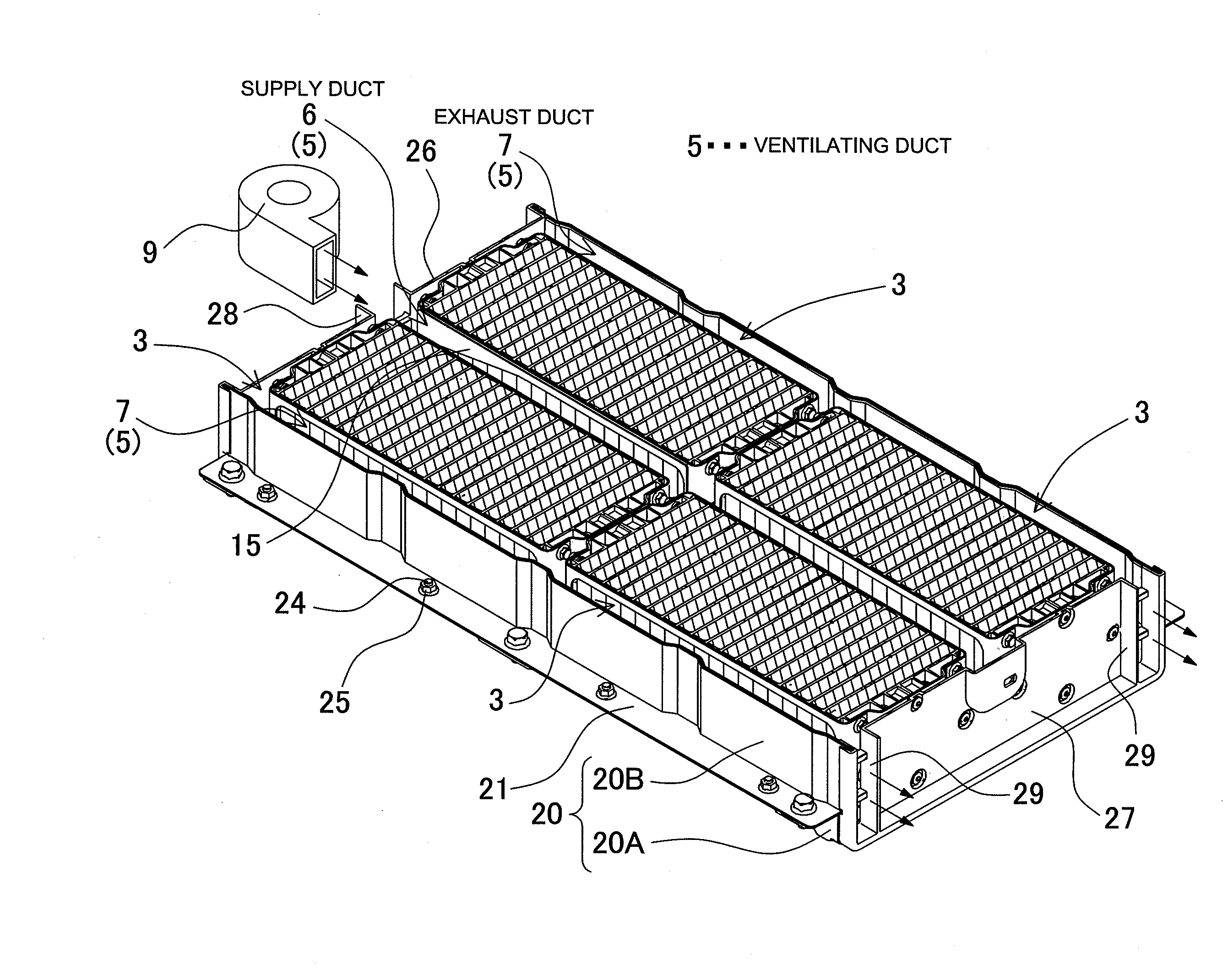
[0050]FIGS. 2-8 show the first embodiment of the present invention, FIGS. 15-18 show the second embodiment of the present invention, FIGS. 19-21 show the third embodiment of the present invention, and FIGS. 22-24 show the fourth embodiment of the present invention. The battery systems described in these embodiments are primarily suitable for use as power sources in electric powered vehicles such as in a hybrid car or plug-in hybrid car, which are powered by both an engine and an electric motor, and in an electric automobile (electric vehicle [EV]), which is powered by an electric motor only. However, the present invention can also be used in non-automotive applications where high output is a requirement.

[0051]In the following embodiments, the battery system is provided with battery blocks 3 having a plurality of battery cells 1 stacked in a manner establishing cooling gaps 4 between the battery ...


PUM

PropertyMeasurementUnit
temperatureaaaaaaaaaa
surface areaaaaaaaaaaa
currentsaaaaaaaaaa

Abstract

The battery system comprises battery blocks 3 having a plurality of stacked battery cells 1, ventilating ducts that are supply ducts and exhaust ducts 7 disposed on each side of the battery blocks 3, and ventilating apparatus 9. Cooling gas is forced to flow from the supply ducts through cooling gaps 4 and into the exhaust ducts 7 to cool the battery cells 1. The battery system has temperature equalizing plates 15 disposed on the supply duct sides of the battery blocks 3. These temperature equalizing plates 15 are provided with mass-flow regulating openings 16 extending in the battery cell 1 stacking direction. The area exposed by the mass-flow regulating openings 16 varies with position in the battery cell 1 stacking direction, and supply duct cooling gas passes through the mass-flow regulating openings 16 into each cooling gap 4 to equalize the temperature of all the battery cells 1.

Description

BACKGROUND OF THE INVENTION[0001]1. Field of the Invention[0002]The present invention relates to a battery system provided with ventilating ducts on both sides of battery blocks having a plurality of horizontally stacked battery cells, and the battery cells are cooled by forced ventilation from the ventilating ducts through cooling gaps in the battery blocks.[0003]2. Description of the Related Art[0004]A battery system, which has many stacked battery cells that are cooled by forced ventilation through cooling gaps between the battery cells, can develop temperature differences between individual battery cells. In particular, as the number of stacked battery cells increases, it becomes difficult to uniformly cool all the battery cells to minimize temperature differences. In a battery system with many battery cells stacked together, it is extremely important to reduce temperature differences between battery cells as much as possible. This is because battery cell temperature differences...

Claims


Application Information

Patent Timeline
Patent Type & Authority Applications(United States)
IPC IPC(8): H01M10/50H01M2/10H01M10/60H01M10/613H01M10/617H01M10/625H01M10/647H01M10/6554H01M10/6557H01M10/6563
CPCH01M10/5004H01M10/5016H01M10/5067H01M10/5032H01M10/5036H01M10/5028H01M10/613H01M10/625H01M10/64H01M10/647H01M10/651H01M10/6563Y02E60/10
Inventor FUJII, KAZUHIRO
Owner SANYO ELECTRIC CO LTD
Why Eureka
Try Eureka