Cooling system for battery pack

a battery pack and cooling system technology, applied in the field of battery pack cooling system, can solve the problems of reducing affecting the performance of the battery pack, and generating a large amount of heat, so as to reduce the degradation of the battery pack. the effect of heat generation from the battery pack, reducing the degradation of the battery pack, and minimizing the temperature differen

Active Publication Date: 2006-05-04
LG ENERGY SOLUTION LTD
View PDF3 Cites 44 Cited by
  • Summary
  • Abstract
  • Description
  • Claims
  • Application Information

AI Technical Summary

Benefits of technology

[0011] Therefore, the present invention has been made in view of the above problems and other conventional technical problems awaiting solution, and it is an object of the present invention to provide a cooling system for a battery pack, which can effectively remove heat generated from battery cells by supplying a refrigerant to the battery cells at a constant flow rate, and can minimize a temperature difference between the battery cells during a cooling process, thereby restricting degradation in the performance of the battery cells and enabling optimal temperature control of the batter cells.
[0012] It is another object of the present invention to provide a battery pack cooling system capable of carrying out a desired cooling operation while achieving a reduction in the size of an overall battery system.
[0017] The battery pack cooling system of the present invention has an effect of reducing the size of an overall battery system because both the refrigerant introduction section and the refrigerant discharge section are formed at the same side of the battery pack. Also, due to the fact that each of the battery modules is associated with a specific one of the refrigerant passages so that the battery modules are independently cooled, the refrigerant can move in the respective passages at a constant flow rate, and a temperature difference between the battery cells can be reduced during a cooling process.

Problems solved by technology

One major problem with vehicles that burn fossil fuels, such as gasoline and diesel, is air pollution.
However, the high output and capacity secondary battery has a problem in that it generates a large amount of heat in a charge / discharge mode thereof.
If the heat of battery cells generated in a charge / discharge mode is not effectively removed, the heat is accumulated, resulting in a degradation of the battery cells.
Firstly, in the case of the conventional battery pack cooling system 10, it is difficult to uniformly distribute the refrigerant, having passed through the introduction section 30, into the respective battery modules 50.
This inevitably results in a wide temperature difference between the battery cells 60.
This doubles a space for the installation of the refrigerant guide members, and thus, undesirably increases the size of an overall battery system.
For these reasons, most currently commercialized battery pack cooling systems are unable to provide optimal temperature control of battery cells, and suffer from an increase in the size of an overall battery system.

Method used


Image

  • Cooling system for battery pack
  • Cooling system for battery pack
  • Cooling system for battery pack

Examples


Embodiment Construction

[0029] Hereinafter, a system for cooling a battery pack according to an embodiment of the present invention will be described with reference to the accompanying drawings. The following description is for the sake of easy understanding of the present invention, and is not intended to limit the scope of the present invention.

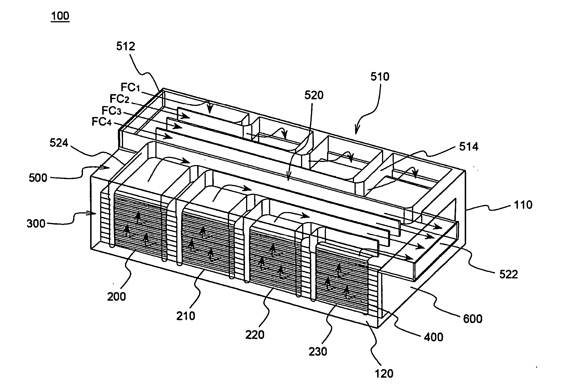
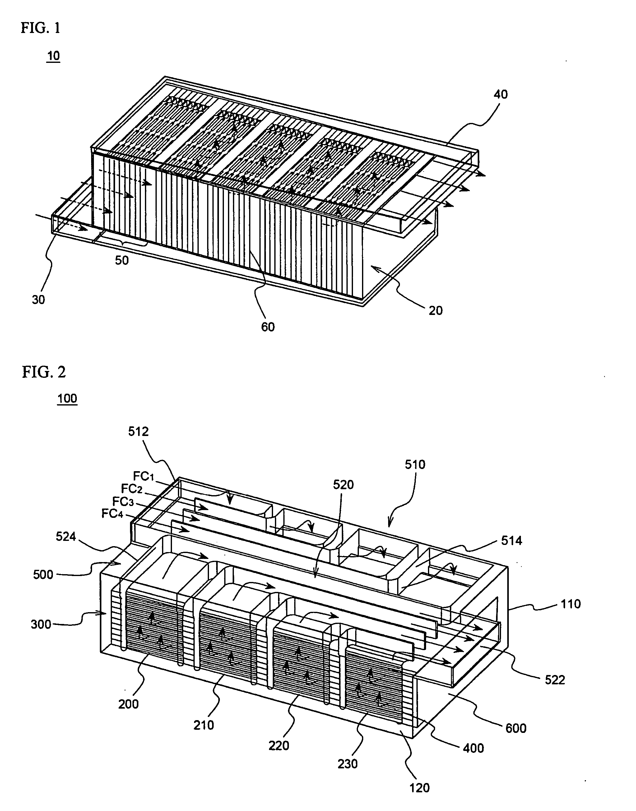
[0030]FIG. 2 is a diagram of a battery pack cooling system according to the present invention, which is shown in partially cutaway view showing the interior. Referring to FIG. 2, the battery pack cooling system 100 includes a battery pack 300 consisting of a plurality of battery modules 200, 210, 220, and 230 electrically connected to each other, and a refrigerant guide member 500 arranged at an upper end surface of the battery pack 300. Each of the battery modules 200, 210, 220, and 230 includes a plurality of battery cells 400 electrically connected to each other.

[0031] The refrigerant guide member 500 includes a refrigerant introduction section 510 and a refr...


PUM


Abstract

Disclosed herein is a cooling system for a battery pack that is usable as a power source of electric vehicles and hybrid-electric vehicles. The cooling system has the effect of effectively dissipating heat generated from battery cells by supplying a refrigerant to the battery cells at a constant flow rate, and of minimizing a temperature difference between the battery cells during a cooling process. This prevents degradation in the performance of the battery cells, and achieves optimal temperature control. Also, the cooling system employs a single refrigerant guide member arranged at a side of the battery pack, resulting in a reduction in the size of an overall battery system.

Description

FIELD OF THE INVENTION [0001] The present invention relates to a cooling system for a battery pack that is usable as a power source of electric vehicles and hybrid-electric vehicles, and, more particularly, to a battery pack cooling system for controlling the temperature of a battery pack, in which a refrigerant introduction section and a refrigerant discharge section are located at the same side of the system and each of a plurality of battery modules has an independent refrigerant passage, whereby a refrigerant passes through a plurality of battery cells of the battery modules at a constant flow rate, resulting in a reduction in a temperature variation between the battery cells as well as the size of an overall battery system. BACKGROUND OF THE INVENTION [0002] One major problem with vehicles that burn fossil fuels, such as gasoline and diesel, is air pollution. To solve such a problem, drawing attention is a technology in which a rechargeable secondary battery is utilized as a po...

Claims


Application Information

Patent Timeline
Patent Type & Authority Applications(United States)
IPC IPC(8): F25D23/12F25B39/02
CPCH01M10/052H01M10/345H01M10/5004H01M10/5016H01M10/5032H01M10/5059H01M10/5065H01M10/5073Y02T10/7011H01M6/42H01M10/613H01M10/625H01M10/647H01M10/6557H01M10/6562H01M10/6566Y02E60/10H01M10/6569
Inventor AHN, JAESUNGWOO, HYOSANGJUNG, DO YANGNAMGOONG, JOHN E.
Owner LG ENERGY SOLUTION LTD
Why Eureka
Try Eureka