Vehicular air conditioning apparatus

a technology of air conditioning apparatus and vehicle, which is applied in the direction of lighting and heating apparatus, manufacturing tools, and vessel construction, etc., can solve the problems of affecting the comfort of passengers in the vehicle compartment, the size of the blower unit having the above-mentioned first and second blowers is inevitably larger than a single blower, and the passenger comfort is impaired adversely, so as to improve the comfort of passengers without sacrificing the space in the vehicle compartment

Active Publication Date: 2013-03-26
HONDA MOTOR CO LTD
View PDF11 Cites 15 Cited by
  • Summary
  • Abstract
  • Description
  • Claims
  • Application Information

AI Technical Summary

Benefits of technology

[0007]A general object of the present invention is to provide a vehicular air conditioning apparatus, which is capable of performing adjusting of temperature separately and independently, respectively, to front and rear seats in a vehicle compartment, without sacrificing a space in the vehicle compartment. The air conditioning apparatus thereby is capable of further improving the comfort of passengers in the vehicle compartment.
[0014]Thus, since the second blower is arranged centrally in the transverse direction of the vehicle with respect to the casing, the second blower can be arranged between the front passenger seat and the driver seat without being mounted inside the dashboard on the passenger seat side. As a result, by the first and second blowers, adjusting of temperature can be performed separately and independently, respectively, to front and rear seats in a vehicle compartment, without sacrificing a space for passengers in the vehicle compartment. The air conditioning apparatus thereby is capable of further improving the comfort of passengers in the vehicle compartment.

Problems solved by technology

However, a blower unit having the above-mentioned first and second blowers is inevitably larger in size than a single blower.
When such a blower unit is arranged in the vehicle, the blower unit tends to project toward the feet side of the front passenger seat in the vehicle, and thus, it is difficult to provide sufficient space for the feet of the passenger.
As a result, the comfort of passengers in the vehicle compartment is impaired adversely.

Method used


Image

  • Vehicular air conditioning apparatus
  • Vehicular air conditioning apparatus
  • Vehicular air conditioning apparatus

Examples


Embodiment Construction

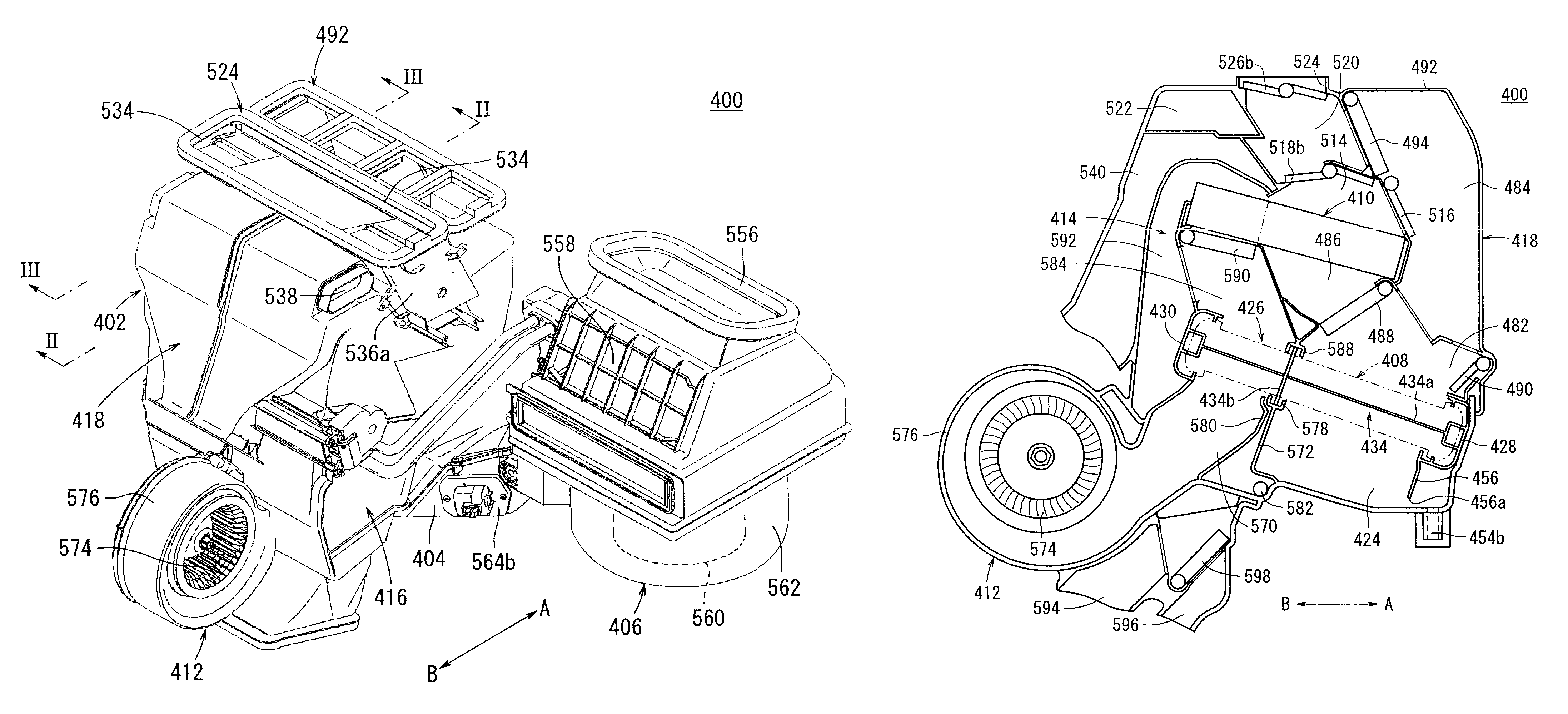
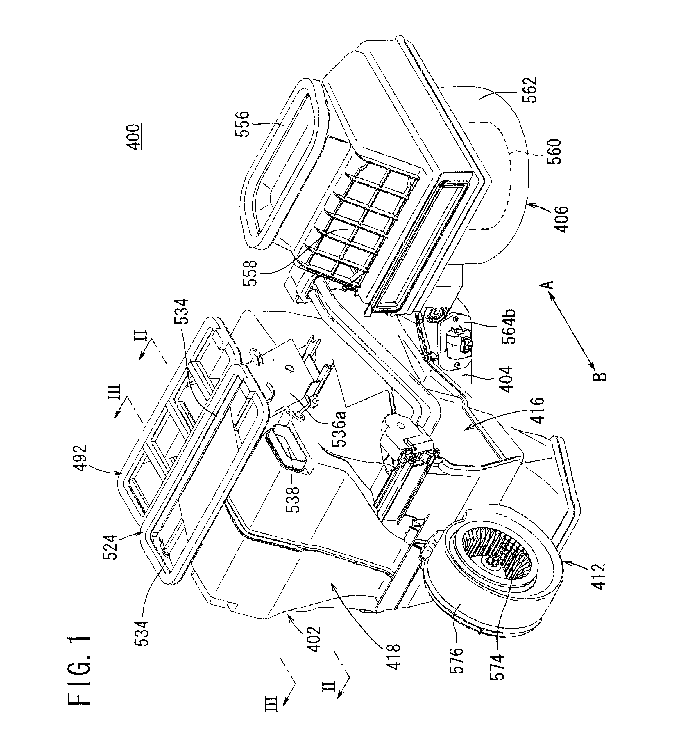
[0050]A preferred embodiment of a vehicular air conditioning apparatus shall be presented and explained in detail below with reference to the accompanying drawings. In FIG. 1, reference numeral 400 indicates a vehicular air conditioning apparatus according to an embodiment of the present invention. The vehicular air conditioning apparatus 400, for example, is installed in a vehicle having three rows of seats arranged along the direction of travel of the vehicle. In the following descriptions, the first row of seats in the vehicle compartment of the vehicle is designated as front seats, the second row of seats is designated as middle seats, and the third row of seats is designated as rear seats. Stated otherwise, the second row of seats (middle seats) and the third row of seats (rear seats) are rear-side seats in the vehicle.

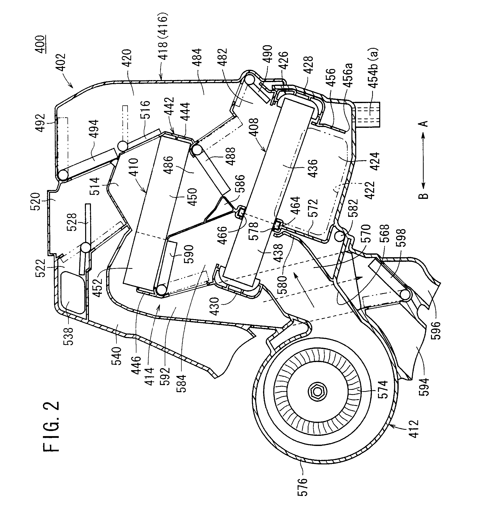
[0051]Further, the vehicular air conditioning apparatus 400 is installed so that the righthand side thereof shown in FIG. 2 (in the direction of arrow A) is orie...


PUM


Abstract

A casing comprises substantially symmetrical first and second divided casings. A second blower unit is provided at a joined region of the first divided casing and the second divided casing. Air is supplied from a first blower unit into the casing, and then, the air cooled by an evaporator and the air heated by a heater core are mixed and supplied to front seats in the vehicle. Air supplied from the second blower unit into the casing is directed toward the front seats and adjusted at a given temperature by a second cooling section of the evaporator and a second heating section of the heater core, and thereafter, supplied to rear seats in the vehicle from a third rear passage which extends so as to surround a first rear passage.

Description

BACKGROUND OF THE INVENTION[0001]1. Field of the Invention[0002]The present invention relates to a vehicular air conditioning apparatus mounted in a vehicle for blowing air, which has been adjusted in temperature by a heat exchanger, into a vehicle compartment, for thereby adjusting the temperature inside the vehicle compartment.[0003]2. Description of the Related Art[0004]In a vehicular air conditioning apparatus that is mounted in a vehicle, internal and external air is introduced into a casing by a blower, and after cooled air, which has been cooled by an evaporator that forms a cooling means, and heated air, which has been heated by a heater core that forms a heating means, are mixed together in the casing at a predetermined mixing ratio, the mixed air is blown out from a defroster blow-out port, a face blow-out port, or a foot blow-out port, whereby adjustment of temperature and humidity in the vehicle compartment is carried out.[0005]With this type of vehicular air conditionin...

Claims


Application Information

Patent Timeline
Patent Type & Authority Patents(United States)
IPC IPC(8): B60H1/00B61D27/00F28F1/00B60H3/00B24D13/00B63J2/00
CPCB60H1/00028B60H2001/00099
Inventor NANAUMI, KYOSUKESETO, TAKAHIROKANEMARU, JUNICHIKAKIZAKI, SHINJI
Owner HONDA MOTOR CO LTD
Why Eureka
Try Eureka