Vehicle steering system
a steering system and vehicle technology, applied in the direction of steering linkages, electrical steering, transportation and packaging, etc., can solve the problems of system not fundamentally solving the problem, the maximum steering angle of the steerable wheel located inside the vehicle's radius cannot be widen, etc., to achieve the effect of sacrificing space in the engine room and enlarge the maximum steering angle of the vehicl
- Summary
- Abstract
- Description
- Claims
- Application Information
AI Technical Summary
Benefits of technology
Problems solved by technology
Method used
Image
Examples
first embodiment
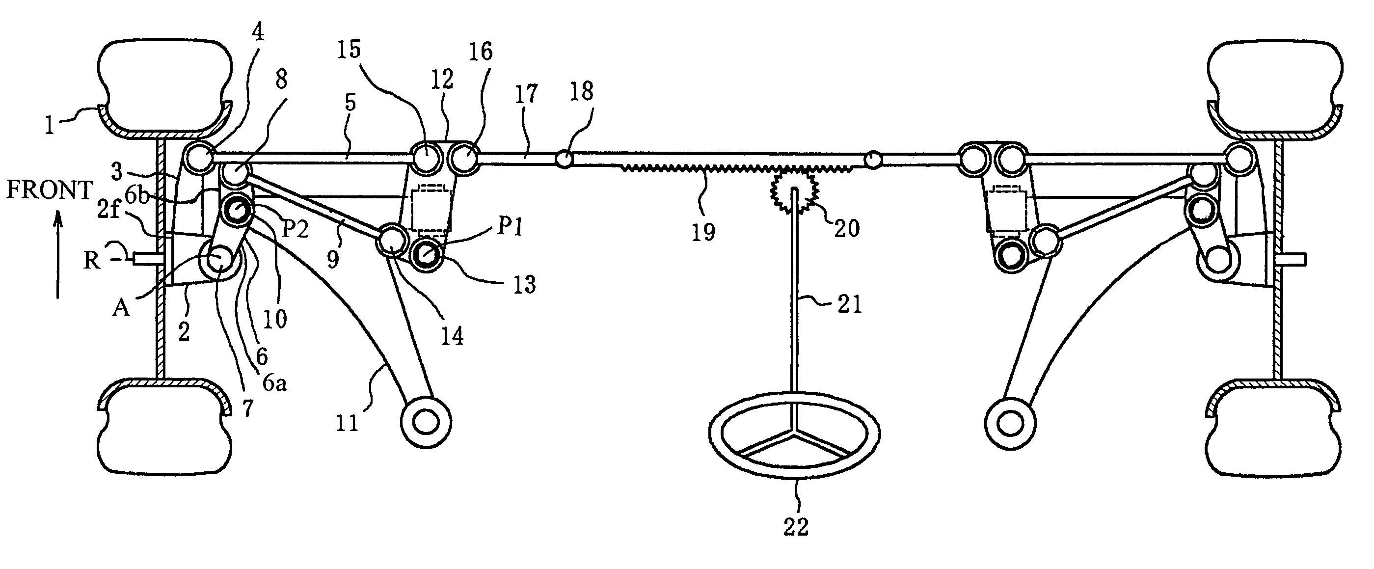
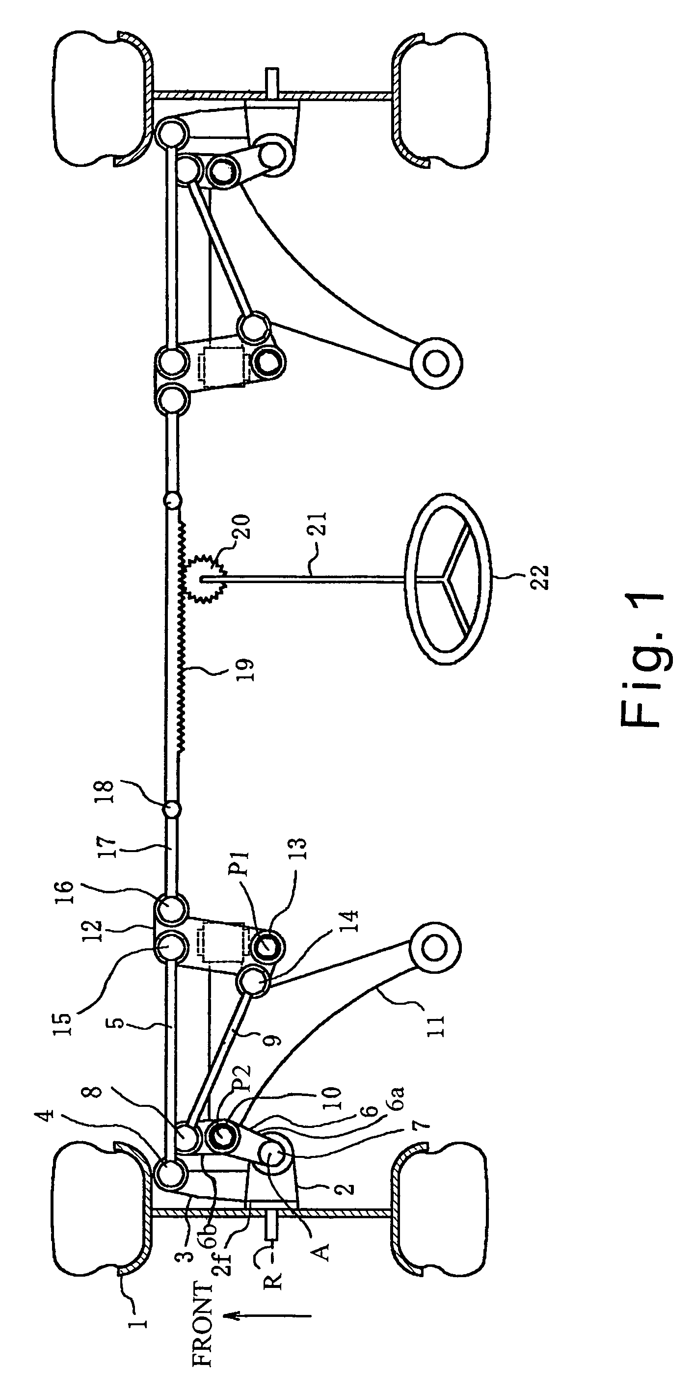
[0038]Referring initially to FIG. 1, a vehicle steering system is illustrated in accordance with a first embodiment of the present invention. The steering system of the present invention avoids contact between a pair of steerable wheels 1 and the wheel housings of the vehicle body because when the wheels 1 turn about their kingpin axes A of a pair of steering knuckles 2 shift outwardly in the widthwise direction of the vehicle. As a result, the steering system widens the maximum steering angle. In particular, FIG. 1 illustrates a rack-and-pinion type steering system that is used in conjunction with a strut type suspension in accordance with the first embodiment of the present invention.
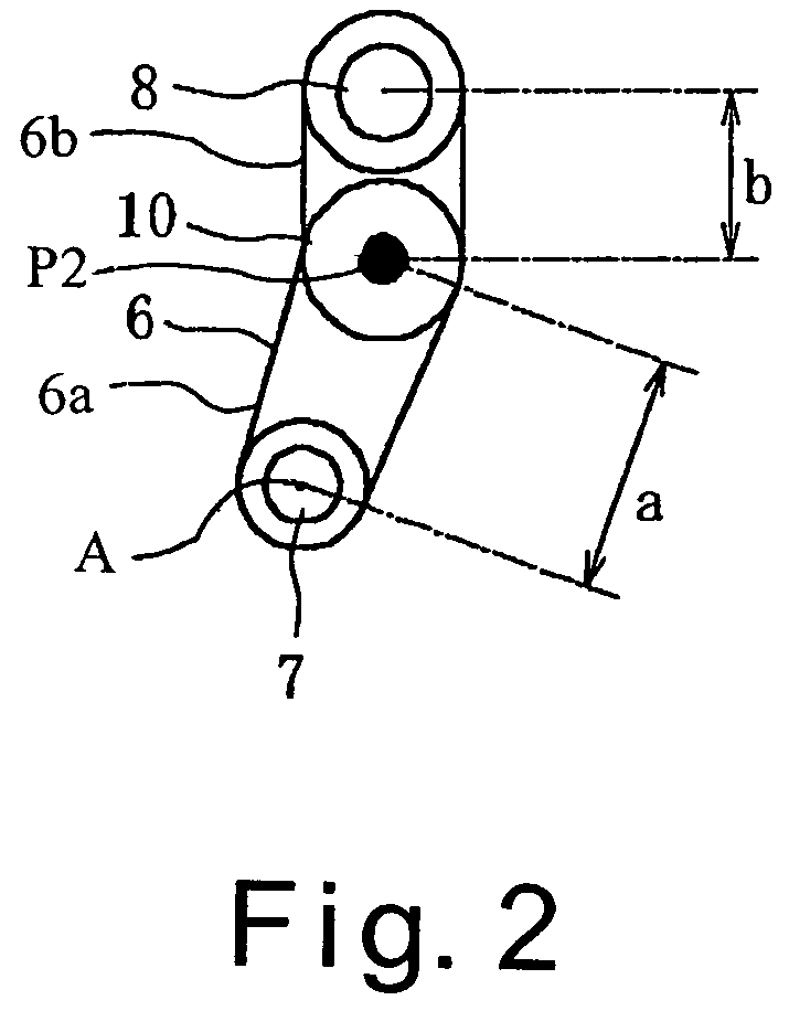
[0039]The vehicle steering system of the first embodiment of the present invention as well as all of the other embodiments of the present invention are designed to shift the steering knuckles 2 outwardly away from the wheel housings of the vehicle body to increase the maximum turning angle. In particu...
second embodiment
[0056]Referring now to FIG. 7, a vehicle steering system is illustrated in accordance with a second embodiment. In view of the similarity between the first and second embodiments, the parts of the second embodiment that are identical or substantially identical to the parts of the first embodiment will be given the same reference numerals as the parts of the first embodiment. Moreover, the descriptions of the parts of the second embodiment that are identical or substantially identical to the parts of the first embodiment may be omitted for the sake of brevity.
[0057]FIG. 7 is a partial diagrammatic top plan view of the left side of the vehicle steering system. The right side of the vehicle steering system is a mirror image of the left side, and thus, the right side of the vehicle steering system will not be illustrated. The vehicle steering system is mechanically connected to the steering shaft 21 through a steering gear box 27 and a pitman arm 28 such that a strut type front suspensi...
third embodiment
[0060]Referring now to FIGS. 8 and 9, a vehicle steering system is illustrated in accordance with a third embodiment. In view of the similarity between the first and third embodiments, the parts of the third embodiment that are identical or substantially identical to the parts of the first embodiment will be given the same reference numerals as the parts of the first embodiment. Moreover, the descriptions of the parts of the third embodiment that are identical or substantially identical to the parts of the first embodiment may be omitted for the sake of brevity.
[0061]FIG. 8 is a partial diagrammatic top plan view of the left side of the vehicle steering system. The right side of the vehicle steering system is a mirror image of the left side, and thus, the right side of the vehicle steering system will not be illustrated. FIG. 9 is a diagrammatic perspective view of the left side of the vehicle steering system shown in FIG. 8 combined with the strut type front suspension. Of course, ...
PUM
 Abstract
Description
Claims
Application Information
 - R&D
- Intellectual Property
- Life Sciences
- Materials
- Tech Scout
- Unparalleled Data Quality
- Higher Quality Content
- 60% Fewer Hallucinations
Browse by: Latest US Patents, China's latest patents, Technical Efficacy Thesaurus, Application Domain, Technology Topic, Popular Technical Reports.
© 2025 PatSnap. All rights reserved.Legal|Privacy policy|Modern Slavery Act Transparency Statement|Sitemap|About US| Contact US: help@patsnap.com


