Miter joint bracket and method of using

a technology of brackets and joints, applied in the field of brackets, can solve the problems of not being able to place brackets on the frame not being able to meet the needs of users, etc., and achieving the effect of reducing the risk of injury, and improving the safety of users

Inactive Publication Date: 2013-03-26
FALCONER RALPH ANTHONY +1
View PDF29 Cites 6 Cited by
  • Summary
  • Abstract
  • Description
  • Claims
  • Application Information

AI Technical Summary

Problems solved by technology

The prior art and building construction professionals recognize the long-standing problems in firmly securing the corners of window shutters, window or door frames, window or door screens, and other such rectangular-frame structures having miter joints at the corners.
As such, the user was limited as to where the bracket could be placed on the frame.
However, in addition to being limited in placement to the outside corner of the frame, this device, because of its triangular shape, tended to be quite heavy, bulky, and cumbersome.
The Hoffman Key K is typically an hour-glass shaped plastic plug that is inserted into an hour-glass shaped cavity C of essentially the same dimensions as the Hoffman Key K and straddling the miter joint J. While the Hoffman Key K suffices to connect adjacent sides of the frame F or shutters, the connection is not as tight or secure as one provided by brackets.
Consequently, the frame F or shutters will eventually begin to wobble and become increasingly unstable over time.
The fact that these devices, with the notable exception of the Hoffman Key, are not in widespread use suggests that they did not solve the connection problem to the satisfaction of the general consuming public or that they were in some way unacceptable to the general consuming public.
Many were bulky, unwieldy, and cumbersome.
Many were unsightly or required too much metal to fabricate the bracket making them expensive to manufacture and again, bulky, unwieldy, and / or cumbersome.
Because of their L-shaped or triangular shapes, most, if not all, had to be positioned at the inner or outer corner of the frame to which they were attached which severely limited the design options available to the user.
Some had numerous moving parts making them expensive to manufacture and, in many cases, difficult to operate.
In sum, the devices disclosed by the prior art suffer numerous shortcomings and disadvantages both individually and collectively:(1) Many of the devices disclosed by the prior art are bulky and cumbersome which makes them difficult to install and unpleasant to look at.(2) Many of the devices disclosed by the prior art are complex in their configuration which makes them difficult and expensive to manufacture, difficult to install, and unpleasant to look at.(3) Many of the devices disclosed by the prior art are have moving parts which eventually loosen and require retightening.
Such devices also tend to require specially machined parts which makes them more expensive to manufacture.(4) Many of the devices disclosed by the prior art cannot or do not prevent the frame to which they are attached from wobbling and, in extreme cases, breaking apart.(5) Most, if not all, of the devices disclosed by the prior art lie flat against the frames to which they are attached which limits the degree to which the frame members can be tightened against one another.(6) Most, if not all of the devices disclosed by the prior art requires alignment and placement at the outer or inner corner and along the edge of the frame to which they were attached.

Method used


Image

  • Miter joint bracket and method of using
  • Miter joint bracket and method of using
  • Miter joint bracket and method of using

Examples


Embodiment Construction

Description—Simplest Embodiment

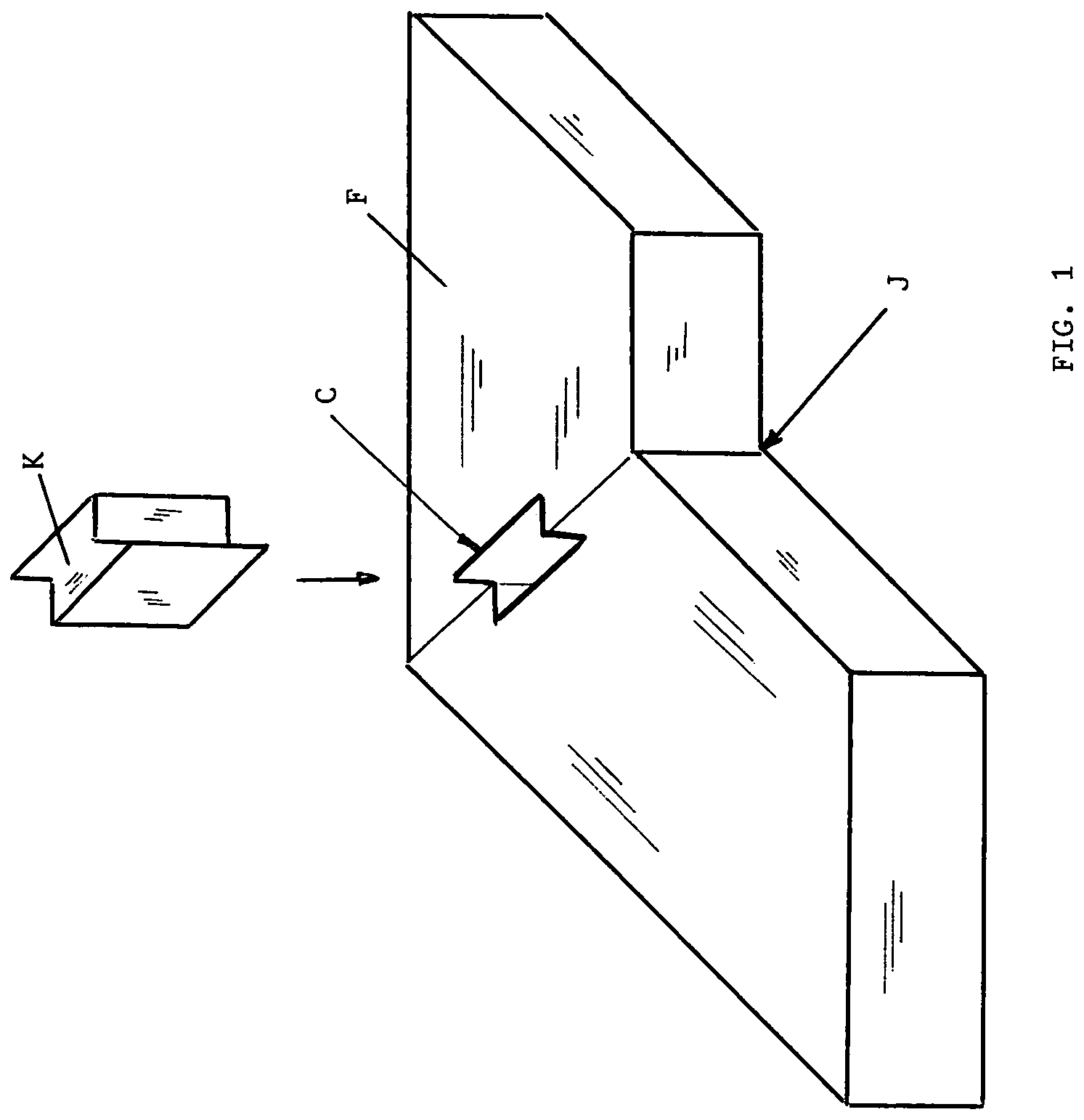
[0055]As mentioned previously, the current industry standard method of securing the corners of a window shutter or a window frame having a miter joint at its corners is the Hoffman Key K which is shown in FIG. 1. The Hoffman Key K is essentially a solid plastic plug shaped like a flat-sided hourglass that is pounded into a cavity C of essentially the same dimensions as the Hoffman Key K and straddling the miter joint J on the frame F. As also mentioned previously, the Hoffman Key K suffices to connect adjacent sides of the frame F or shutters but the connection is not as tight or secure as one provided by brackets. Consequently, the frame F or shutters will eventually begin to wobble and become increasingly unstable over time, especially when the frame is exposed to large variations in temperature and moisture.

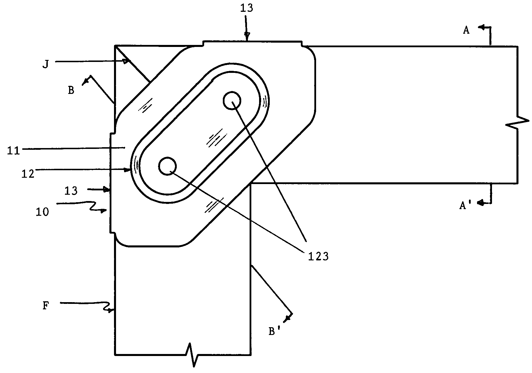
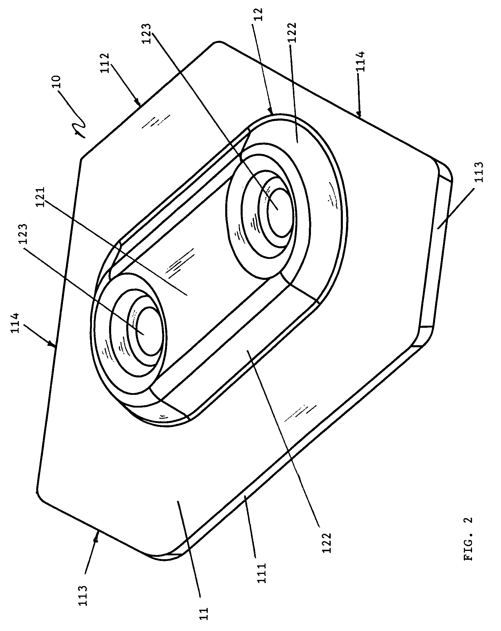
[0056]FIG. 2 shows a downward-looking rear perspective of the simplest embodiment of present invention. The bracket 10 is an oblate hexagonal ba...


PUM

PropertyMeasurementUnit
angleaaaaaaaaaa
lengthaaaaaaaaaa
obtuse angleaaaaaaaaaa

Abstract

A miter joint bracket and method of using comprised of a base-plate having an oblate-hexagonal shape, a flat-roofed dome rising vertically from the base-plate, apertures drilled into the dome's flat roof to accommodate fasteners drilled or nailed through the apertures and into both sides of the miter joint of the frame to which the bracket is attached. The upper edges of the miter joint are drawn up into the space underneath the dome which pulls the upper edges slightly apart but forces the lower edges of the miter joint closer together thereby creating a tighter and more aesthetically appealing joint on the view-side of the shutter or frame to which the bracket is attached.

Description

FEDERALLY SPONSORED RESEARCH[0001]Not ApplicableSEQUENCE LISTING OR PROGRAM[0002]Not ApplicableField of the Invention[0003]The present invention relates generally to the field of brackets for connecting and securing the side sections of rectangular frames such as picture frames and window shutter frames. More particularly, the present invention relates to the field of brackets for connecting and securing the side sections of rectangular frames such as picture frames and window shutter frames having mitered joints on the corners of the rectangular frames.BACKGROUND OF THE INVENTIONDescription of the Prior Art[0004]The prior art and building construction professionals recognize the long-standing problems in firmly securing the corners of window shutters, window or door frames, window or door screens, and other such rectangular-frame structures having miter joints at the corners. While the miter joint presents an aesthetically appealing configuration for joining adjacent sides of a win...

Claims


Application Information

Patent Timeline
Patent Type & Authority Patents(United States)
IPC IPC(8): F16B1/00
CPCE06B3/9641E06B3/9645F16B12/10F16B12/46Y10T403/42Y10T29/49963Y10T403/73Y10T403/725Y10T403/7096Y10T403/555F16B2200/67F16B2200/65
Inventor FALCONER, RALPH ANTHONYFALCONER, SCOTT ALLEN
Owner FALCONER RALPH ANTHONY
Why Eureka
Try Eureka