Mirror-based assemblies, including lateral transfer hollow retroreflectors, and their mounting structures and mounting methods

a technology of mirror-based assemblies and retroreflectors, applied in the direction of mirrors, instruments, mountings, etc., can solve the problems of thermal effects that may translate into degradation of optical performance, reduced stress, and design not necessarily optimized for thermal effects, so as to improve the mirror-base assembly, and minimize thermal expansion or contraction.

Pending Publication Date: 2021-10-21
PLX
View PDF6 Cites 0 Cited by
  • Summary
  • Abstract
  • Description
  • Claims
  • Application Information

AI Technical Summary

Benefits of technology

[0009]In accordance with the invention an improved mirror-base assembly is provided. The mirror-based assembly has at least one mirror panel, at least one support member, and at least three connection regions between the at least one support member and the at least one mirror panel, comprising at least a first connection region comprising a miter joint connection region and at least a second connection region comprising a non-miter joint connection region and at least a third connection region, wherein the at least the first mirror panel is connected to the at least one support member to minimize thermal expansion or contraction of the at least the first mirror panel.
[0010]In accordance with an additional aspect of the invention, an improved roof mirror assembly is provided. The roof mirror assembly has at least two mirror panels, at least one support members, and at least three connection regions between the at least one support member and the at least one mirror panel, comprising at least a first connection region comprising a miter joint connection region and at least a second connection region comprising a non-miter joint connection region and a third connection region, wherein the at least one mirror panel is connected to the at least one support member to minimize thermal expansion or contraction of the at least one mirror panel.
[0011]In accordance with yet another aspect of the invention, A lateral transfer hollow retroreflector device, comprising at least two subassemblies, wherein each of the at least two subassemblies comprising at least one mirror panel, at least one support member, and at least three connection regions between the at least one support member and the at least one mirror panel, comprising at least a first connection region comprising a miter joint connection region and at least a second connection region comprising a non-miter joint connection region, wherein each of the at least one mirror panels of the at least two subassemblies are connected to the at least one support member to minimize thermal expansion or contraction of the at least one mirror panel.
[0012]In accordance with yet another aspect of the invention, an improved lateral transfer hollow retroflector assembly is provided. The lateral transfer hollow retroflector assembly has at least two subassemblies, wherein each subassembly comprises at least one mirror panel, at least one support member, at least three connection regions between the at least one support member and the at least one mirror panel, comprising at least a first connection region comprising a miter joint connection region and at least a second connection region comprising a non-miter joint connection region, wherein the at least one mirror panel is connected to the at least one support member to minimize thermal expansion or contraction of the at least one mirror panel.
[0013]In accordance with at least another aspect of the invention, an improved lateral transfer hollow retroflector assembly is provided. The lateral transfer hollow retroflector assembly has at least two subassemblies, wherein the first two subassemblies comprises at least two mirror panels, at least three support member, at least six connection regions between the at least one support member and the at least one mirror panel, comprising at least a first connection region comprising a miter joint connection region and at least a second connection region comprising a non-miter joint connection region, wherein the at least one mirror panel is connected to the at least one support member to minimize thermal expansion or contraction of the at least one mirror panel.
[0014]In accordance with a further aspect of the invention, an improved method for a mirror-base assembly is provided. The method for a mirror-base assembly having at least one mirror panel, at least one support member, at least three connection regions between the at least one support member and the at least one mirror panel, comprising at least a first connection region comprising a miter joint connection region and at least a second connection region comprising a non-miter joint connection region and a third connection region, wherein the at least one mirror panel is connected to the at least one support member to minimize thermal expansion or contraction of the at least one mirror panel. The steps of the method are assembling the one or more support members having miter joint structure to a mirror panel by the second connection region having a miter joint, and assembling the one or more support members having non-miter joint structure to a mirror panel by the first connection region having a non-miter joint.

Problems solved by technology

While some approaches may be easiest for assembly and manufacturing, specifically regarding part complexity and tolerances, such a design is not necessarily optimized for thermal effects such as contraction and expansion.
Furthermore, during thermal excursion of significant temperatures, these types of thermal effects may translate into degradation of optical performance, such as but not limited to, surface flatness, beam deviation, wavefront shape, peak-to-valley or rms values or any combination thereof.
With such a design, there may be some reduction in stresses caused by thermal expansion or contraction, but not fully optimized by only using a single geometry.
Additionally, fully chamfered edges be more challenging for manufacturing efforts without the full benefits of performance.

Method used


Image

  • Mirror-based assemblies, including lateral transfer hollow retroreflectors, and their mounting structures and mounting methods
  • Mirror-based assemblies, including lateral transfer hollow retroreflectors, and their mounting structures and mounting methods
  • Mirror-based assemblies, including lateral transfer hollow retroreflectors, and their mounting structures and mounting methods

Examples


first embodiment

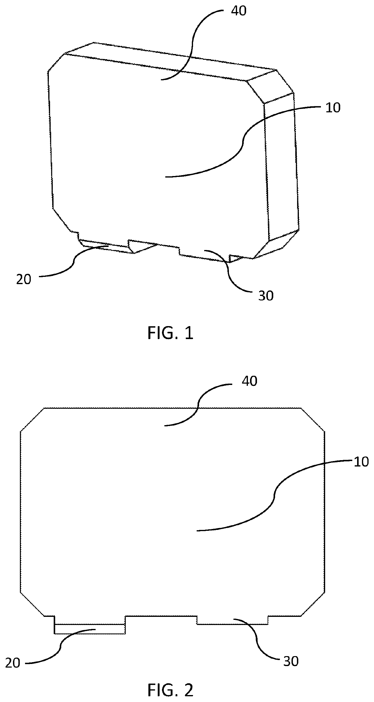
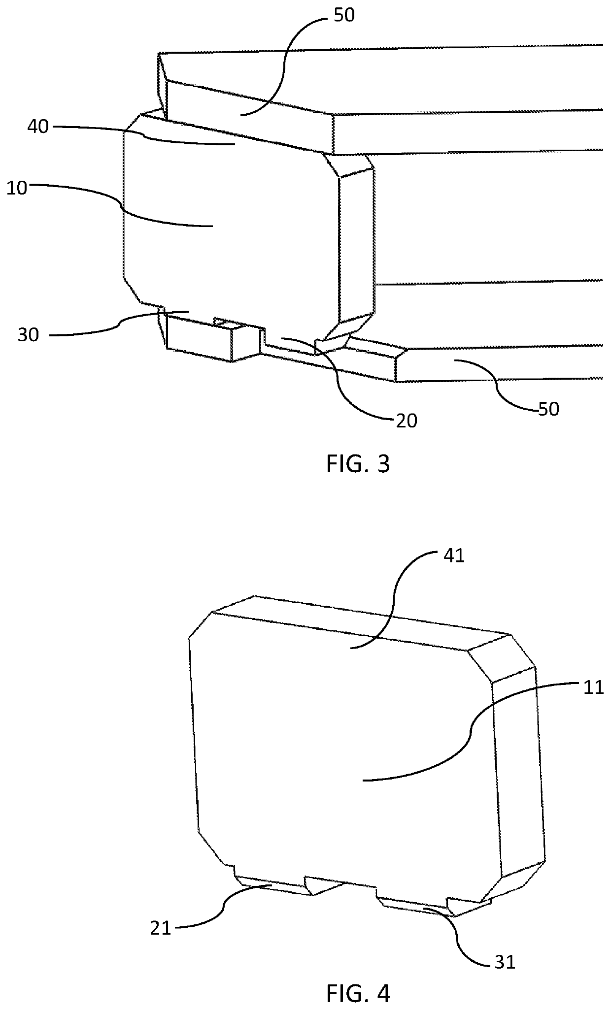
[0070]The first preferred embodiment of the mirror-based assembly is depicted in FIGS. 1-3, showing the mirror panel (10) having a first connection region (20), a second connection region (30) and a third connection region (40). In this first embodiment showing a single mirror panel as an example, the first connection region has a miter structure (20), the second region has a pad structure (30) and the third region has a flat structure (40). In FIG. 3 the mirror panel (10) is assembled within the mirror-based assembly to the support member (50).

second embodiment

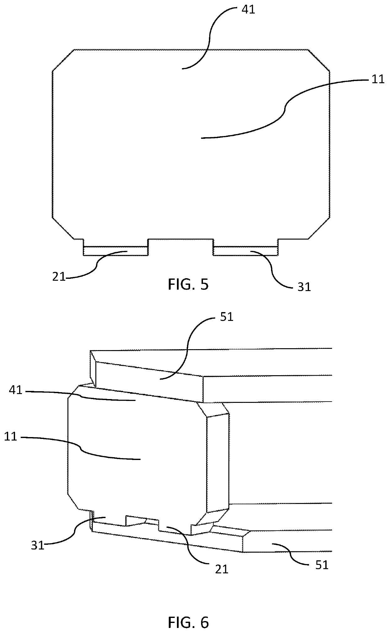
[0071]The second preferred embodiment of the mirror-based assembly is depicted in FIGS. 4-6, showing the mirror panel (11) having a first connection region (21), a second connection region (31) and a third connection region (41). In this second embodiment of a mirror-based assembly, there are two connection regions having a miter structures (21,31), and the third region has a flat structure (41). In FIG. 6 the mirror panel is assembled within the mirror-based assembly to the support member (51).

third embodiment

[0072]The third preferred embodiment of the mirror-based assembly is depicted in FIGS. 7-9, showing the mirror panel (12) having a first connection region (22), a second connection region (32) and a third connection region (42). In this third embodiment of a mirror-based assembly, the first connection region has a miter structure (22), the second region has a pad structure (32) and the third region has a pin structure (42). In FIG. 9 the mirror panel is assembled within the mirror-based assembly to the support member (52).

[0073]The fourth preferred embodiment of the mirror-based mirror is depicted in FIGS. 10-12, showing the mirror panel (13) having a first connection region (23), a second connection region (33) and a third connection region (43). In this second embodiment of a mirror-based assembly, there are two connection regions having a miter structures (23,33), and the third region has a pin structure (43). In FIG. 12 the mirror panel is assembled within the mirror-based assem...


PUM


Abstract

An improved mirror-based assembly is provided. The mirror-based assembly has at least one mirror panel, at least one support member, and at least three connection regions between the at least one support member and the at least one mirror panel, comprising at least a first connection region comprising a miter joint connection region, at least a second connection region comprising a non-miter joint connection region, and at least a third connection region, wherein the at least one mirror panel is connected to the at least one support member to minimize thermal expansion or contraction of the at least one mirror panel and a method for assembling the same.

Description

BACKGROUND OF THE INVENTION[0001]This invention relates to the field of mirror-based assemblies, for use as and in optical assemblies. Examples of such mirror-based assemblies include, but are not limited to, flat mirror panels, hollow retroreflectors, roof mirror assemblies, lateral transfer hollow retroreflectors, and periscopes.[0002]Optical assemblies containing mirror panels have typically been connected to support members by simple methods, such as utilizing all flat regions to mate the parts together. While some approaches may be easiest for assembly and manufacturing, specifically regarding part complexity and tolerances, such a design is not necessarily optimized for thermal effects such as contraction and expansion. Furthermore, during thermal excursion of significant temperatures, these types of thermal effects may translate into degradation of optical performance, such as but not limited to, surface flatness, beam deviation, wavefront shape, peak-to-valley or rms values ...

Claims


Application Information

Patent Timeline
Patent Type & Authority Applications(United States)
IPC IPC(8): G02B7/198G02B5/08G02B5/12
CPCG02B7/198G02B5/12G02B5/08G02B7/008G02B7/182
Inventor VISHNIA, ITAI
Owner PLX
Why Eureka
Try Eureka