Bypass thermal adjuster for vacuum semiconductor processing

a technology of thermal adjuster and vacuum semiconductor, which is applied in the direction of charging manipulation, lighting and heating apparatus, furniture, etc., can solve the problems of limiting the ability to move multiple workpieces independently, occupying a small space for handling and storing work pieces such as wafers, and occupying a large space for storag

Active Publication Date: 2013-03-26
BLUESHIFT TECH +2
View PDF23 Cites 54 Cited by
  • Summary
  • Abstract
  • Description
  • Claims
  • Application Information

AI Technical Summary

Problems solved by technology

Due to the high cost of space within a vacuum environment, the space for handling and storing work pieces such as wafers is generally kept small.
However, these space constraints can limit the ability to move multiple workpieces independently within the vacuum, and traffic bottlenecks can occur in buffers between processes.
As fabrication processes grow in size and complexity, the difficulties of thermal management and wafer movement become greater.

Method used


Image

  • Bypass thermal adjuster for vacuum semiconductor processing
  • Bypass thermal adjuster for vacuum semiconductor processing
  • Bypass thermal adjuster for vacuum semiconductor processing

Examples


Embodiment Construction

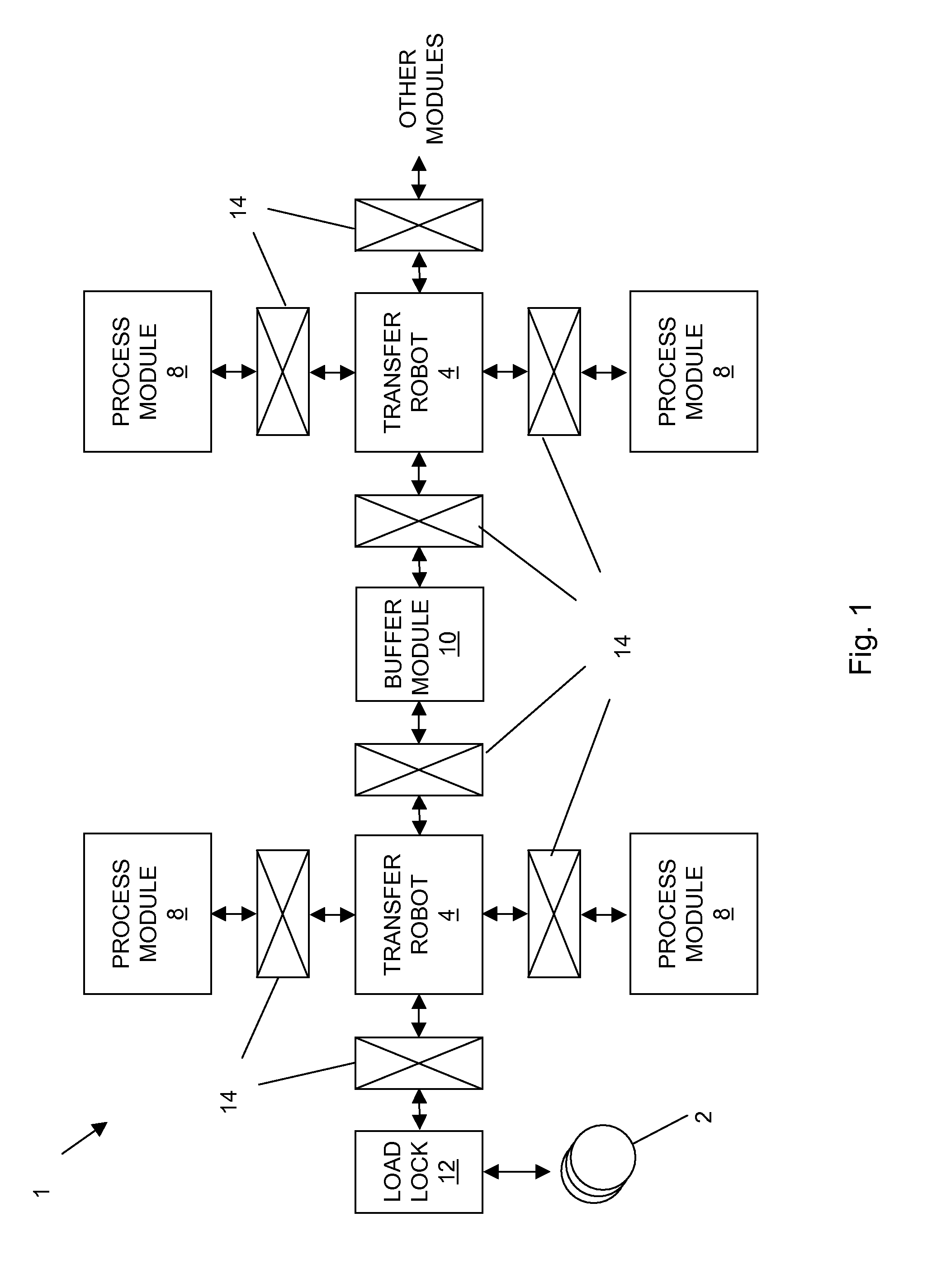
[0045]FIG. 1 shows a generalized layout of a semiconductor manufacturing system. The system 1 may include one or more wafers 2, a load lock 12, one or more transfer robots 4, one or more process modules 8, one or more buffer modules 10, and a plurality of slot valves 14 or other isolation valves for selectively isolated chambers of the system 1, such as during various processing steps. In general operation, the system 1 operates to process wafers for use in, for example, semiconductor devices.

[0046]Wafers 2 may be moved from atmosphere to the vacuum environment through the load lock 12 for processing by the process modules 8. It will be understood that, while the following description is generally directed to wafers, a variety of other objects may be handled within the system 1 including a production wafer, a test wafer, a cleaning wafer, a calibration wafer, or the like, as well as other substrates (such as for reticles, magnetic heads, flat panels, and the like), including square ...


PUM


Abstract

A bypass thermal adjuster, which may be placed between two robots, provides a chamber for isolation and thermal control of wafers while permitting other wafers to be passed through the adjuster by the robots.

Description

RELATED APPLICATIONS[0001]This application is a continuation-in-part of U.S. application Ser. No. 11 / 679,829 filed on Feb. 27, 2007 now abandoned, which claims the benefit of U.S. Prov. App. No. 60 / 777,443 filed on Feb. 27, 2006, and is a continuation-in-part of U.S. application Ser. No. 10 / 985,834 filed on Nov. 10, 2004 now U.S. Pat. No. 7,458,763 ,which claims the benefit of U.S. Prov. App. No. 60 / 518,823 filed on Nov. 10, 2003 and U.S. Prov. App. No. 60 / 607,649 filed on Sep. 7, 2004.[0002]This application also claims the benefit of the following U.S. applications: U.S. Prov. App. No. 60 / 779,684 filed on Mar. 5, 2006; U.S. Prov. App. No. 60 / 779,707 filed on Mar. 5, 2006; U.S. Prov. App. No. 60 / 779,478 filed on Mar. 5, 2006; U.S. Prov. App. No. 60 / 779,463 filed on Mar. 5, 2006; U.S. Prov. App. No. 60 / 779,609 filed on Mar. 5, 2006; U.S. Prov. App. No. 60 / 784,832 filed on Mar. 21, 2006; U.S. Prov. App. No. 60 / 746,163 filed on May 1, 2006; U.S. Prov. App. No. 60 / 807,189 filed on Jul. ...

Claims


Application Information

Patent Timeline
Patent Type & Authority Patents(United States)
IPC IPC(8): B65G49/07
CPCB65G25/02B65G37/00H01L21/67161H01L21/67196H01L21/67742H01L21/67745H01L21/67748H01L21/68792
Inventor VAN DER MEULEN, PETER
Owner BLUESHIFT TECH
Why Eureka
Try Eureka