Edge curling tool

a tool and tool body technology, applied in shaping tools, forging/pressing/hammering apparatuses, and safety devices for shaping tools, etc., can solve the problems of affecting the freedom of movement of actuators, affecting the accessibility of tools as a whole, and voluminous flange tools of this type, so as to facilitate the flange of components

Active Publication Date: 2013-04-02
FFT PRODIONSSYST
View PDF19 Cites 72 Cited by
  • Summary
  • Abstract
  • Description
  • Claims
  • Application Information

AI Technical Summary

Benefits of technology

[0008]It is an object of the invention to make it easier to flange a component part along a peripheral strip which exhibits different angular positions with respect to an adjacent region of the component part in the longitudinal direction, and to provide a roll-flanging tool which fulfills this object.
[0016]Preferably, the flanging rollers protrude freely. In such embodiments, the first flanging roller is freely accessible over a complete circumference about the first rotational axis, over the axial length of its rolling or flanging area, i.e. the tool does not comprise any other structure which axially overlaps with the rolling area of the first flanging roller. However, embodiments in which the rolling area of the first flanging roller is freely accessible as viewed from the second flanging roller are also advantageous. Lastly, an embodiment in which at least the side of the rolling area of the first flanging roller which faces away from the second flanging roller is freely accessible is also regarded as being advantageous. The same applies analogously to the second flanging roller, i.e. in preferred embodiments, its rolling area protrudes in an extension of the second arm of the tool beyond all the other structures of the tool in this region, freely accessible from all sides, or is at least not axially overlapped up to its front end by another structure of the tool in the region between the two arms, i.e. towards the first flanging roller.

Problems solved by technology

Component parts in which the peripheral strip, along which a flanging web is to be folded over, points at an angle to an adjacent region of the component part, and in which the angular position of the peripheral strip changes in the longitudinal direction, are for example problematic with respect to accessibility and consequently the freedom of movement of an actuator bearing a roll-flanging tool.
In addition, the angular position of the tool also generally has to be altered in the course of the flanging steps which are to be successively performed, wherein the tool as a whole is often cumbersome.
However, flanging tools of this type are in many cases voluminous and problematic if the space available is restricted.
The spring-elastic support likewise increases the volume of the tool and increases the complexity and accordingly also the price.

Method used


Image

  • Edge curling tool
  • Edge curling tool
  • Edge curling tool

Examples


Embodiment Construction

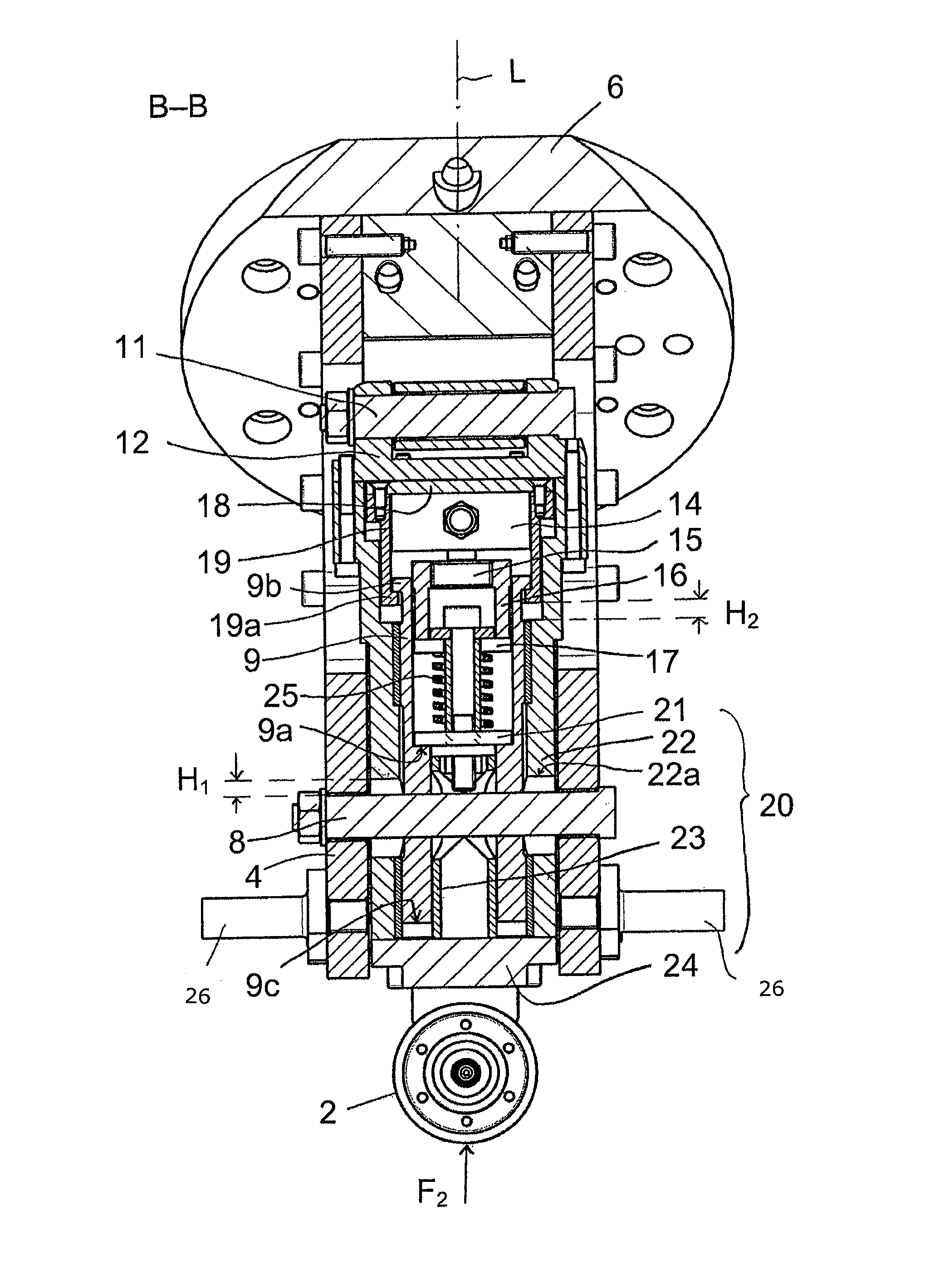
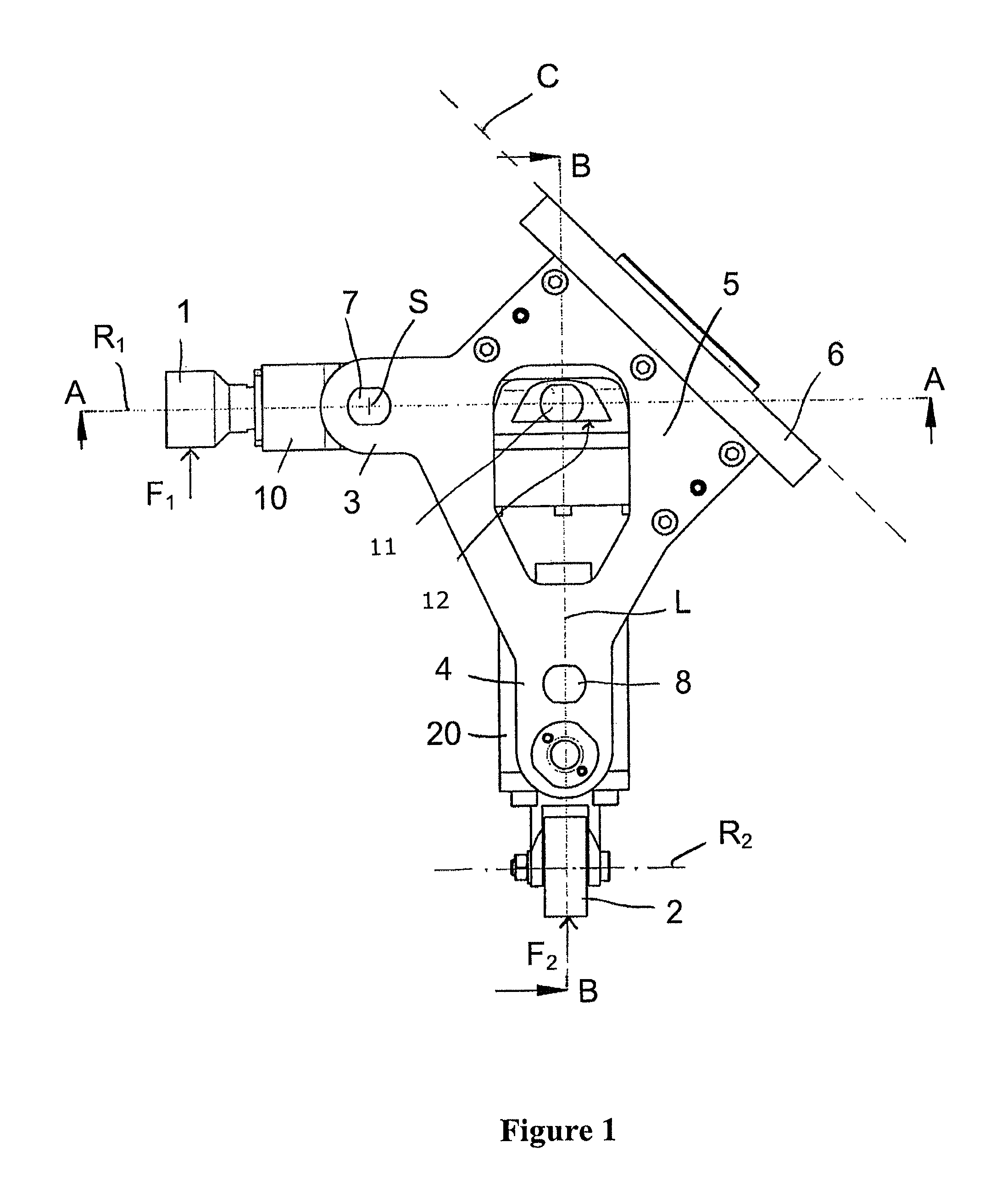
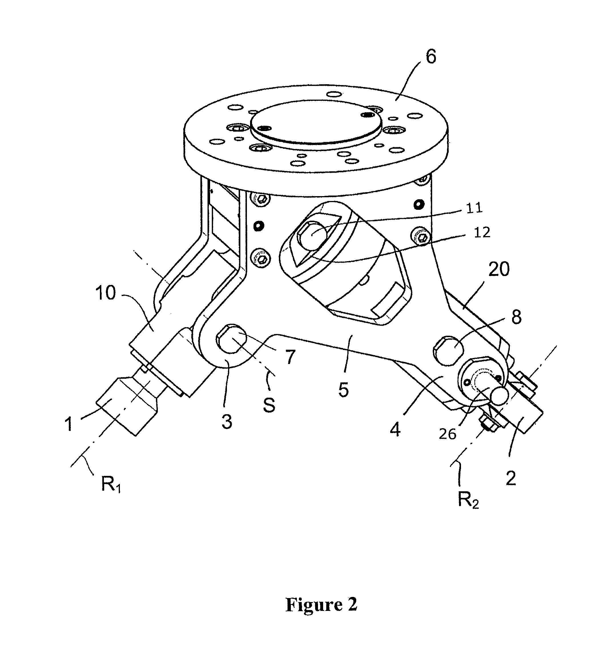
[0031]FIGS. 1 and 2 show a roll-flanging tool in a lateral view and a perspective view. The tool is designed as a tool head for an industrial robot or other actuator which can be moved spatially in a comparable way. It comprises a first flanging roller 1, a second flanging roller 2 and a bearing structure which serves as a fixed framework and mounts the components of the tool, in particular the flanging rollers 1 and 2. The tool does not comprise any other flanging rollers beyond the flanging rollers 1 and 2. The flanging roller 1 is supported on the bearing structure such that it can be pivoted by means of the transmission means 10, and the flanging roller 2 is supported on the bearing structure such that it can be linearly moved by means of the transmission means 20. The tool is at least suitable for being connected to an actuator of said type.

[0032]The bearing structure comprises a first arm 3 and a second arm 4, as well as a connection portion 5 from which the arms 3 and 4 proje...


PUM

PropertyMeasurementUnit
angleaaaaaaaaaa
obtuse angleaaaaaaaaaa
angleaaaaaaaaaa

Abstract

A roll-flanging tool, including a bearing structure having a connector, by which the tool can be connected via a connection plane to an actuator which can be moved spatially. A first arm and a second arm are spread apart from each other and connected to each other in a connection portion which includes the connector. A first flanging roller is mounted on an end of the first arm which faces away from the connection plane, such that it can be rotated about a first rotational axis which extends along the first arm and pierces the connection plane. A second flanging roller is mounted on an end of the second arm which faces away from the connection plane, such that it can be rotated about a second rotational axis. The first rotational axis intersects or crosses a perpendicular dropped onto the second rotational axis, in or on the roll-flanging tool.

Description

[0001]This application is the U.S. national phase application of PCT International Application No. PCT / EP2008 / 004338, filed May 30, 2008, which claims priority to German Patent Application No. DE 20 2007 007 838.2, filed Jun. 1, 2007, the contents of such applications being incorporated by reference herein in their entirety.BACKGROUND OF THE INVENTION[0002]1. Technical Field[0003]The invention relates to a roll-flanging tool for flanging component parts, preferably for producing hemmed connections between two or more component parts. The tool is or can be fastened to an actuator which can be moved spatially, for example an end of an arm of an industrial robot, or other framework which is comparable with regard to the connection. The tool can in particular be used in the manufacture of vehicles and vehicle parts, preferably in the series production of automobiles.[0004]2. Description of the Related Art[0005]In automobiles, particular regions of the body, for example wheel arches, or ...

Claims


Application Information

Patent Timeline
Patent Type & Authority Patents(United States)
IPC IPC(8): B21D7/02
CPCB21D19/043B21D39/023B21D39/021B21D19/04
Inventor REITH, STEFANTODZEY, DETLEFRITZ, ALBERT
Owner FFT PRODIONSSYST
Why Eureka
Try Eureka