Foil bearing supported motor with adjustable thrust bearing cap

a thrust bearing and supporting technology, applied in the direction of dynamo-electric components, fuel cells, electric generators, etc., can solve the problems of low speed of conventional bearings, damage to the motor stator, and large size of ball bearings and sleeves, so as to save energy and facilitate flanges , the effect of saving energy

Active Publication Date: 2018-06-26
R & D DYNAMICS CORPORATION
View PDF17 Cites 0 Cited by
  • Summary
  • Abstract
  • Description
  • Claims
  • Application Information

AI Technical Summary

Benefits of technology

[0009]The present invention runs at high speed, thus the blower is smaller and weighs less than machines with comparable pressure rise and flow. Also, the blower has features that separates the process gas and leakage flow away from the motor stator and allows the motor stator be cooled in another fashion.
[0010]Moreover, certain embodiments of the invention incorporate a thrust bearing that is adjustable without disassembling the compressor. This is by contrast to conventional thrust bearings, which are shimmed to a non-adjustable position. According to these embodiments, a motor thrust bearing, which normally is needed to be adjusted with shims, instead is adjusted with a combination back cap and thrust cap screw that can set the preload of the bearing either before test, during assembly, or during testing.
[0011]Particular advantages of the present invention include the following: There is no possibility of oil contamination in the process gas since the machine is oil-free. The heat that is generated by the bearings is moved into the process gas which is useful for energy savings. The blower mounts easily on flanges which are part of the machine. The cooling scheme allows the bearings and motor to run cooler which allows the machine to run faster. The cooling scheme reduces the number of parts in the compressor, resulting in a lower manufacturing cost. There is not a motor housing for the stator or housing for the machine, which saves on the part count, protects the motor from process gas, and improves cooling of the stator. Cooling fins are part of the motor stator laminations, which aid in the cooling of the machine. This also reduces part count and removes the thermal resistance that would occur if there were separate pieces. The protective end caps and inner sleeve on the stator, along with the potting material or encapsulant, protects the windings of the stator and the stator in general from contacting the process gas and damaging the stator. The motor has an adjustable thrust bearing cavity that can change the preload of the thrust bearing without the need of shims, and can change the preload of the bearings while the machine is running. It is a more efficient assembly of the machine and reduces part count. It also removes constant assembly and disassembly of machines to “tune” the preload of the thrust bearings.

Problems solved by technology

Existing technologies that use conventional bearings (ball bearings and sleeve bearings) run at low speed and as a result will be larger and less efficient.
Additionally, these bearings often require oil lubrication that can contaminate the fuel cell and result in damage.
Furthermore, in the process gas there might be liquid or caustic material that might damage the motor stator.

Method used


Image

  • Foil bearing supported motor with adjustable thrust bearing cap
  • Foil bearing supported motor with adjustable thrust bearing cap
  • Foil bearing supported motor with adjustable thrust bearing cap

Examples


Embodiment Construction

[0020]Embodiments of the invention are shown in the drawings and are described as relating to a typical application of fuel cell fuel or air delivery (either stationary or mobile). Other applications of the invention, however, may include, for example: aeration units, printing systems, and air knives. The machine can be mounted in a vertical or horizontal direction.

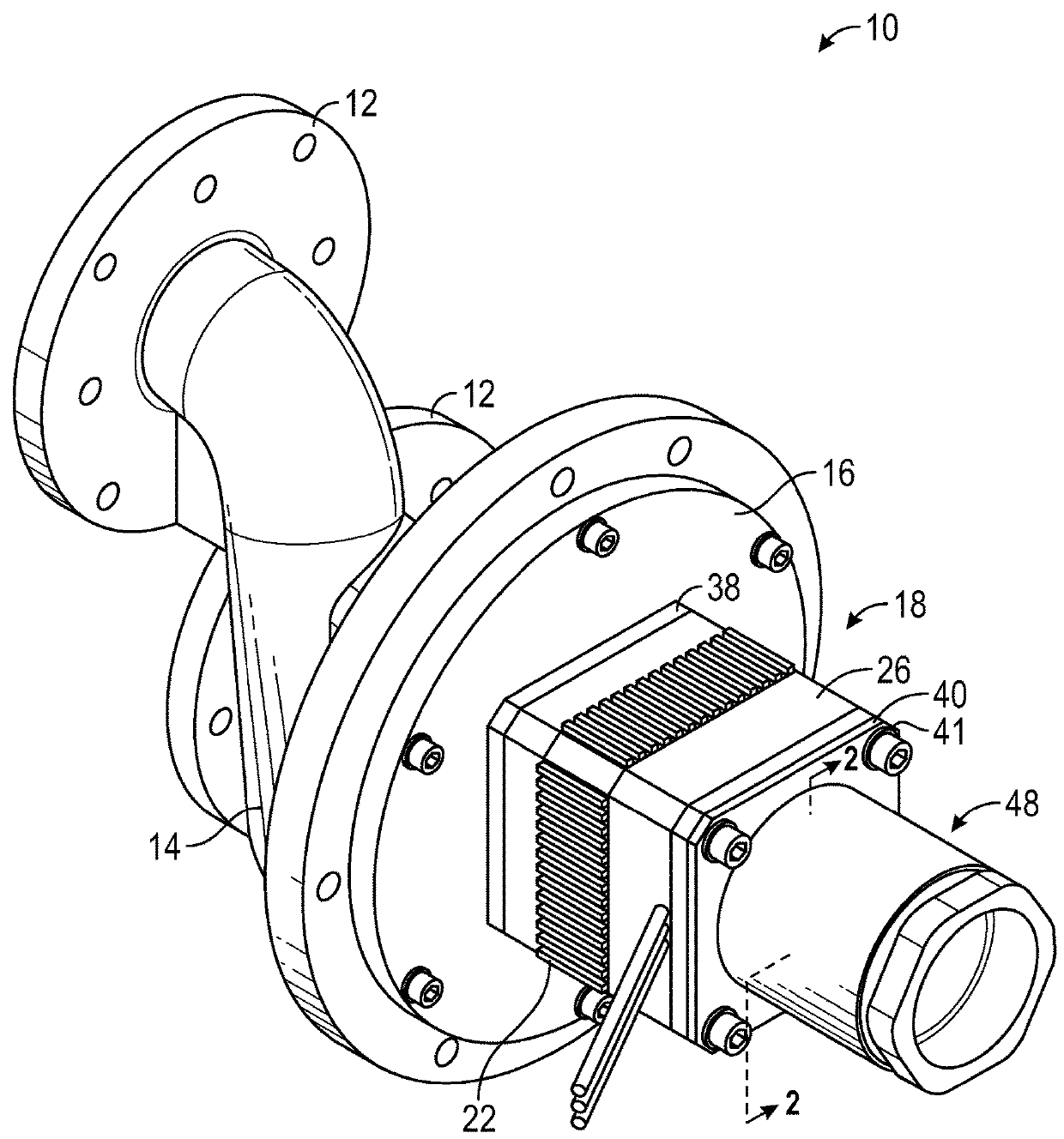
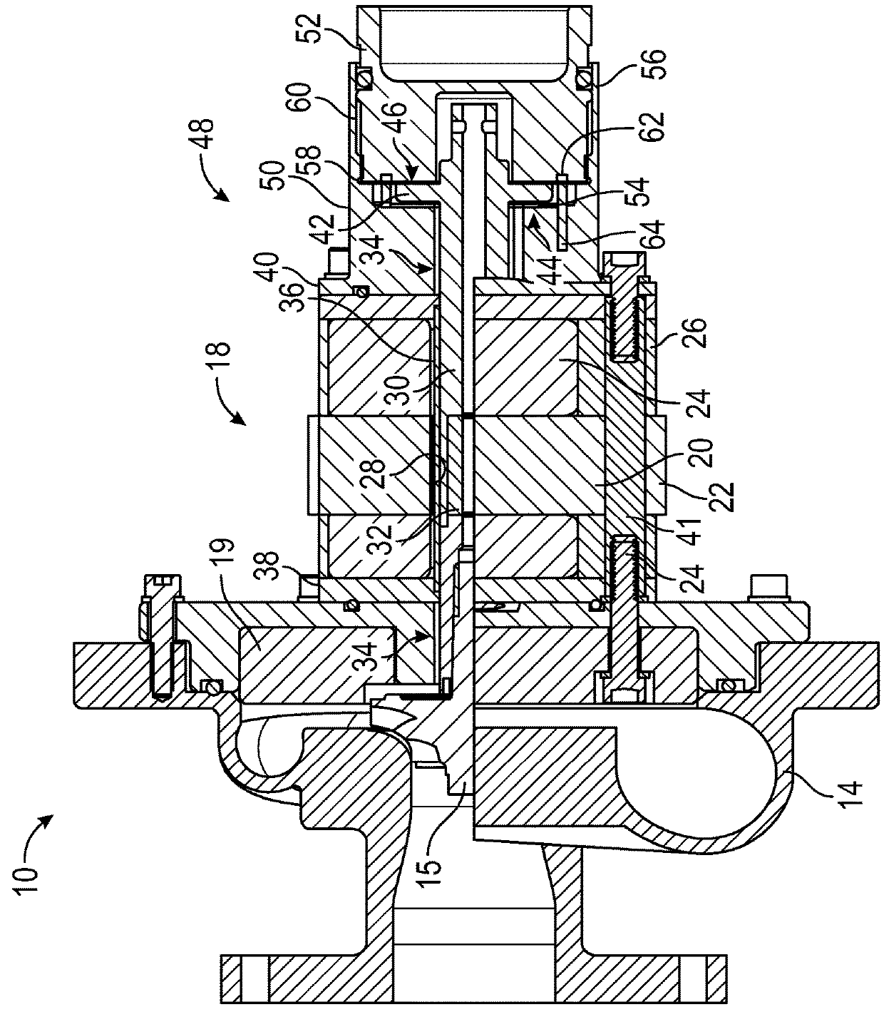
[0021]An isometric view of the blower 10 is shown in FIG. 1; FIG. 2 shows internal parts of the blower 10 in a cross-sectional view. In certain embodiments, flanges 12 that connect to a customers system are integrated into a volute 14 of the blower so as to reduce part number and decrease leaks of the process gas. The volute 14 houses an impeller 15, and supports a journal bearing sleeve 16, e.g., by way of cap screws. From the journal bearing sleeve 16 a motor, including a stator 18, is supported by way of hollow rods 41. The volute also may house a vaneless diffuser 19, through which the hollow rods 14 can be bolted; al...


PUM

PropertyMeasurementUnit
speedaaaaaaaaaa
thermal conductiveaaaaaaaaaa
inner diameteraaaaaaaaaa

Abstract

An electric motor includes a stator; an annular end cap, fastened at a first end of the stator; a threaded seat that is mounted at an outward end face of the annular end cap for receiving a first gas foil thrust bearing; a shaft, inserted through the stator, through the annular end cap, and through the threaded seat; a thrust runner mounted at an end of said shaft adjacent the threaded seat; a first gas foil thrust bearing that is mounted into the threaded seat, adjacent a face of the thrust runner facing the stator; a bearing cap that has a threaded fitting by which it is attached onto the threaded seat; and a second gas foil thrust bearing that is mounted into the bearing cap adjacent to a face of the thrust runner opposite the first gas foil thrust bearing.

Description

CROSS-REFERENCE TO RELATED APPLICATIONS[0001]This application claims the benefit under 35 USC § 119(e) of U.S. Provisional Application No. 62 / 174,088, filed Jun. 11, 2015 and is incorporated herein by reference.BACKGROUND[0002]Technical Field[0003]The invention relates to motor-driven equipment for movement of gases through fuel cells. Particular embodiments of the invention relate to centrifugal compressors.[0004]Discussion of Art[0005]All fuel cells require hydrogen, natural gas, process fluid / gas to the anode side to operate. Movement of gas is typically accomplished with a blower. Existing technologies that use conventional bearings (ball bearings and sleeve bearings) run at low speed and as a result will be larger and less efficient. In fuel cells the largest parasitic load in the system is the air blower. Thus, any improvement in blower efficiency has a dramatic effect on the system overall efficiency. Additionally, these bearings often require oil lubrication that can contami...

Claims


Application Information

Patent Timeline
Patent Type & Authority Patents(United States)
IPC IPC(8): H02K15/12H02K5/18H02K5/12H02K5/02H02K5/20H01M8/04082H02K5/167
CPCH02K5/02H01M8/04201H02K5/12H02K5/18H02K5/20H02K5/1672H02K2205/03Y02E60/50H02K5/207H02K5/203
Inventor NELSON, ALEXANDER R.BUCKLEY, CHARLES W.AGRAWAL, GIRIDHARI L.
Owner R & D DYNAMICS CORPORATION
Why Eureka
Try Eureka