Advanced-powered sliding or guillotine door trap system for cage or corral-type animal traps

a technology of sliding or guillotine doors and trap systems, which is applied in the field of advanced-powered cage trap systems to achieve the effect of enhancing the allowable us

Active Publication Date: 2013-04-09
DEKALB KIRK ALAN
View PDF15 Cites 12 Cited by
  • Summary
  • Abstract
  • Description
  • Claims
  • Application Information

AI Technical Summary

Benefits of technology

[0006]A trap door system is provided in the present invention that has an advanced powered guillotine or sliding door system. The features of the invention enhance the allowable uses of a guillotine door or sliding door type animal trap. More than one powered door may be incorporated into the trap door system. In particular, a guillotine style cage trap may include a powered sliding door on opposing ends and use a double support mechanism in connection with the trigger for the trap.
[0009]The present invention allows more varied use of cage traps on inclines, uneven ground, in bad weather conditions, and in water or under water. The powered sliding door for guillotine or sliding door traps may operate at various positions and angles, and enhances the capability of the trapping process through speed and force. Because of such speed and force, the powered sliding door allows the trap to be used in water to catch rapidly moving animals moving down a run or a channel, wherein the door slices through water rapidly and operates more effectively than a common swing-style cage door or a gravity powered slide door.
[0010]A more open side door trap may be provided with a powered sliding door to improve trapping of animals and adaptation of the trap to improved cage designs or corral type traps.

Problems solved by technology

Another disadvantage is that a standard gravity door catch mechanism may allow the door to open if the trap is turned over.

Method used


Image

  • Advanced-powered sliding or guillotine door trap system for cage or corral-type animal traps
  • Advanced-powered sliding or guillotine door trap system for cage or corral-type animal traps
  • Advanced-powered sliding or guillotine door trap system for cage or corral-type animal traps

Examples


Embodiment Construction

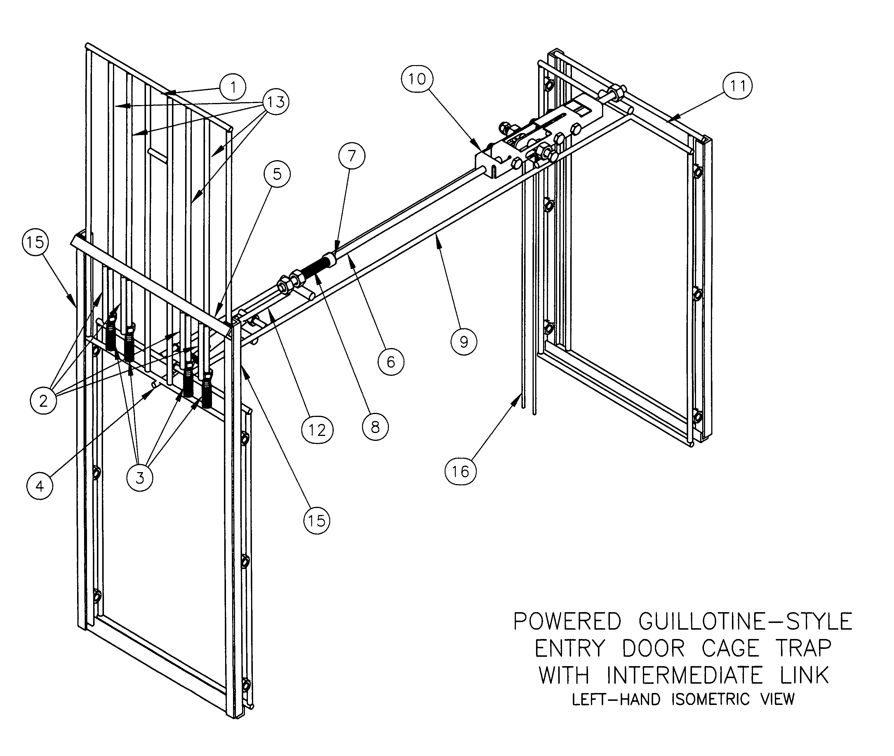
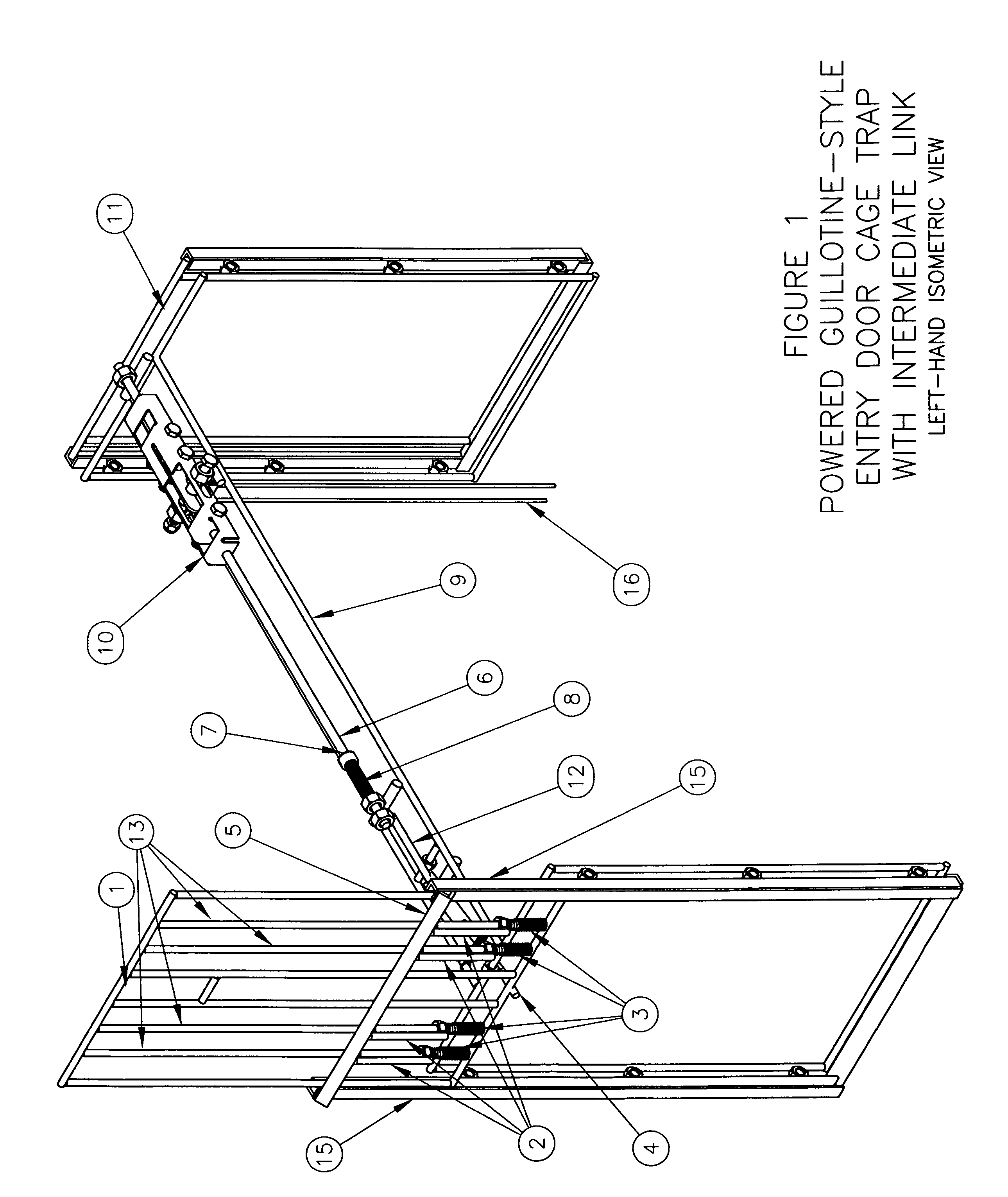
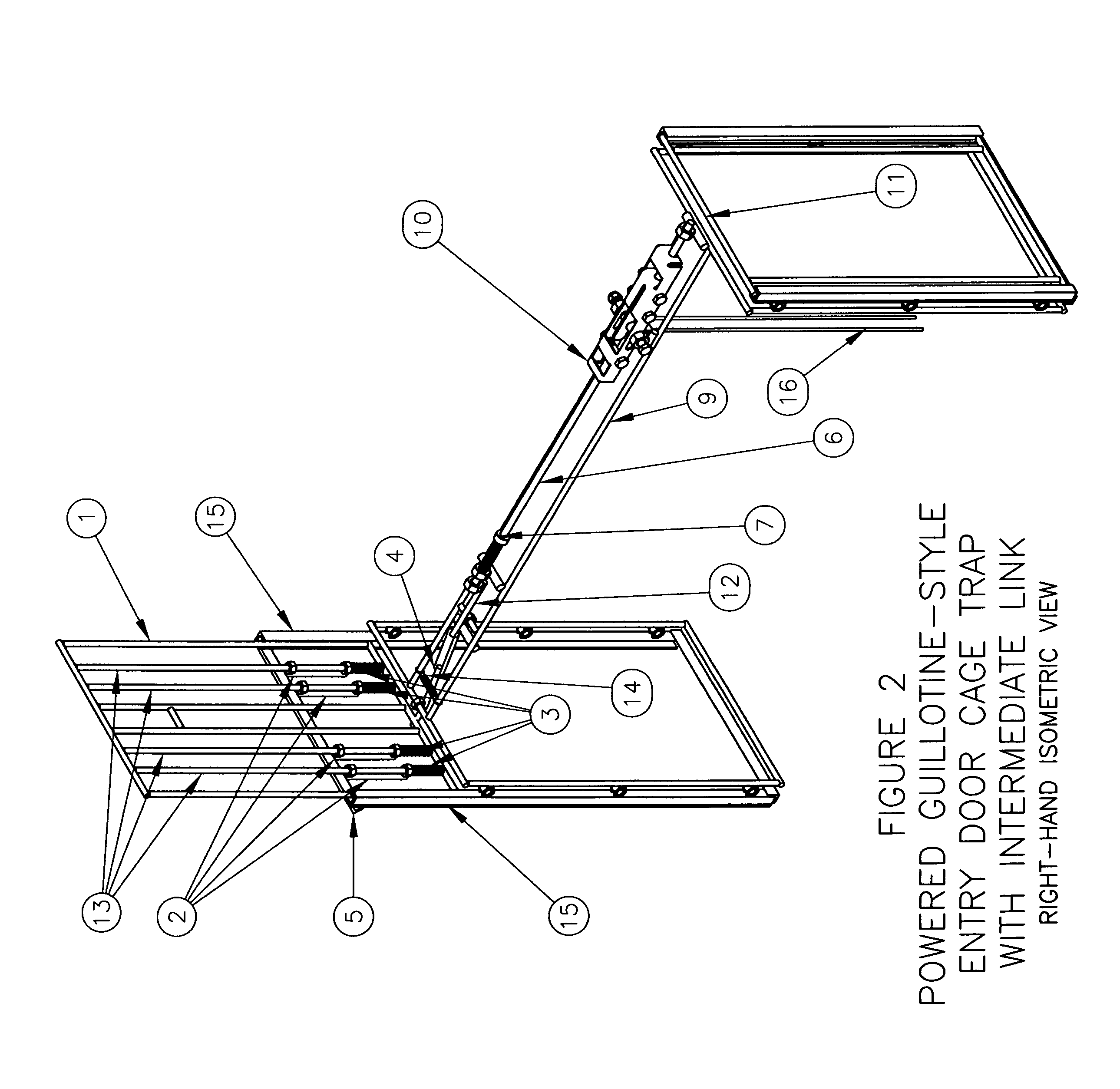
[0017]FIG. 1, FIG. 2, FIG. 3 and FIG. 4 illustrate a trap door system in accordance with an embodiment of the invention. The figures show a front entry advanced powered guillotine door cage-type trap frame 9. The guillotine door or sliding door cage-type trap is generally rectangular in shape like that of a box. However, those in the art should appreciate that guillotine door or sliding door cage-type traps may have any shape that has an interior volume large enough to house an animal to be trapped.

[0018]The trap door system is used on a trap having a cover or housing (not shown) fashioned of mesh, webbing, metal, PVC, or other materials and designs. The trap includes a trap frame 9 that can be made of multiple structural elements. The trap includes an entry door 1, which in the present invention is enhanced by a powered trap door system further described below.

[0019]The trap door system includes an intermediate release assembly or release assembly. The release assembly is triggered...


PUM


Abstract

A trap door system for sliding trap doors or guillotine-style traps has a door guide assembly in which a door of a trap slides. The system provides a powered door using a door spring arming assembly having compression springs and spring slides situated on door supports. With the door open, the spring slides compress the compression springs and engage a door spring stop to bias the door toward a closed position. The door is spring loaded so that when a support mechanism with trigger is operated to release a catch assembly, the door rapidly closes. The catch assembly includes a spring to bias the catch arm to position for locking the door once closed. The support mechanism may be situated to operate multiple doors using the system.

Description

BACKGROUND OF THE INVENTION[0001]1. Field of the Invention[0002]The present invention relates to powered cage trap systems, and, particularly, to an improved spring powered guillotine door system for cage traps.[0003]2. Description of the Related Art[0004]As the years have progressed, the use of powered cage trap systems has evolved slowly. Some traps now use power trigger systems, and progress has sped up and set new expectations for powered door systems to be used for cage traps and corral traps. These expectations have yet to be met with respect to a powered guillotine door system, as such innovation has been slow to evolve until the present invention because of the know abilities and limitations of triggers and trigger assemblies. However, a need exists for a more advanced powered guillotine door system that will increase the ability of a guillotine door cage trap to be used on an incline or to be set at angles not allowed with a standard gravity door. A further need exists for ...

Claims


Application Information

Patent Timeline
Patent Type & Authority Patents(United States)
IPC IPC(8): A01M23/00
CPCA01M23/20
Inventor DEKALB, KIRK ALAN
Owner DEKALB KIRK ALAN
Why Eureka
Try Eureka