

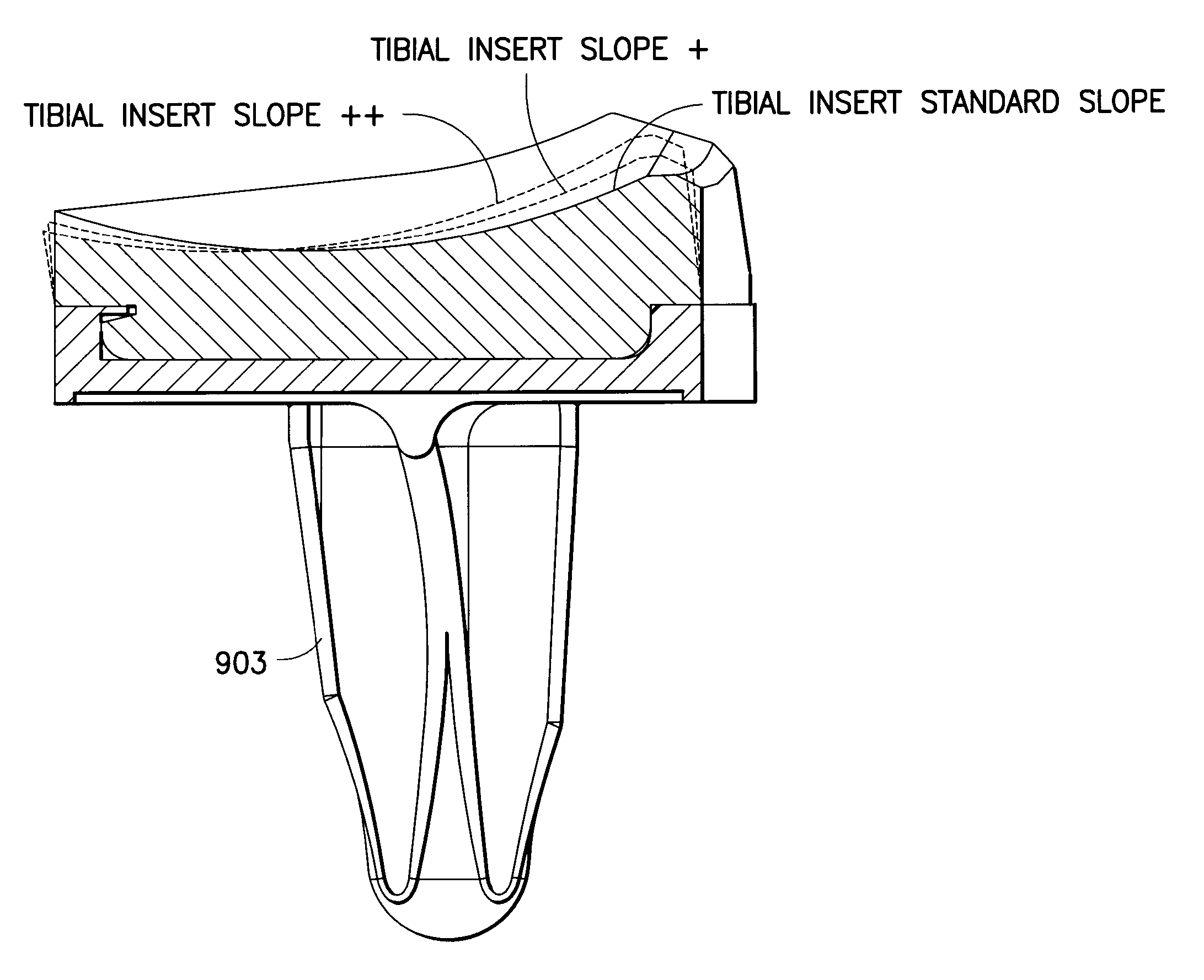
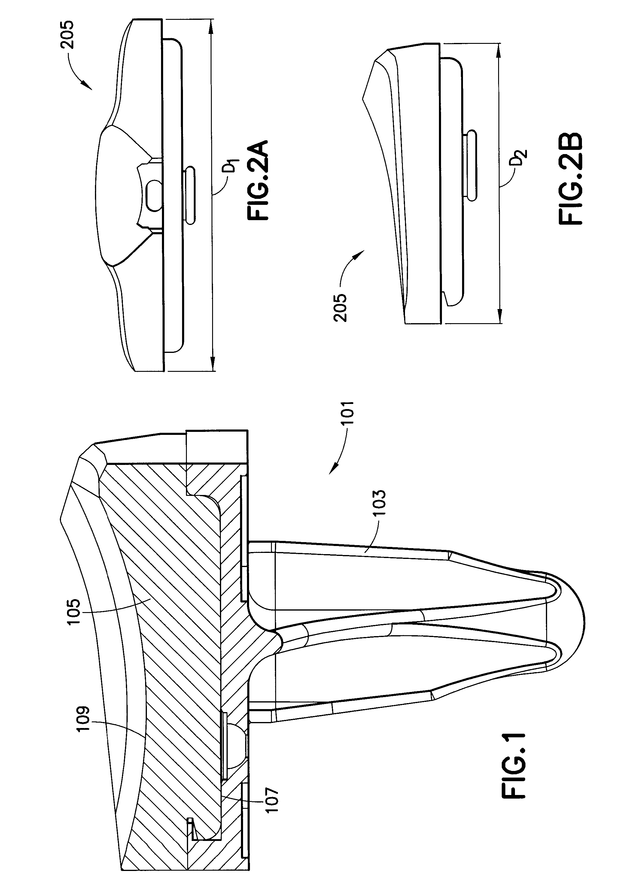
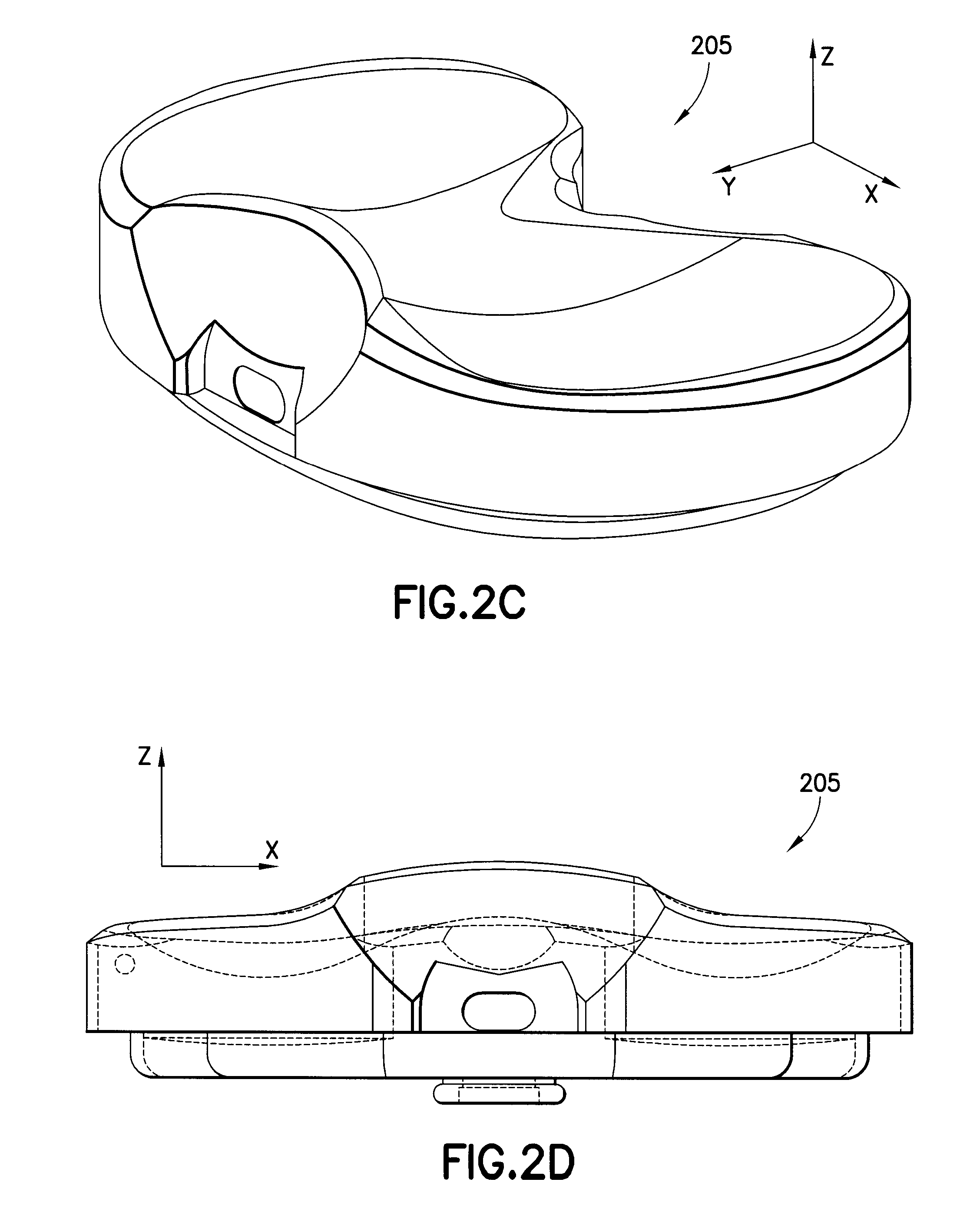
Knee prosthesis system with at least a first tibial portion element (a tibial insert or tibial trial) and a second tibial portion element (a tibial insert or tibial trial), wherein each of the first tibial portion element and the second tibial portion element has a different slope
a technology of tibial pcl and tibial joint, which is applied in the field of knee prosthesis system, can solve the problems of each of these approaches can have negative consequences for pcl function and cr total knee replacement performance, and damage the pcl (and/or the tibial pcl attachment)
- Summary
- Abstract
- Description
- Claims
- Application Information
AI Technical Summary
Benefits of technology
Problems solved by technology
Method used
Image

Examples
Embodiment Construction
[0041]Detailed embodiments of the present invention are disclosed herein; however, it is to be understood that the disclosed embodiments are merely illustrative of the invention that may be embodied in various forms. In addition, each of the examples given in connection with the various embodiments of the invention are intended to be illustrative, and not restrictive. Further, any figures are not necessarily to scale, some features may be exaggerated to show details of particular components. Therefore, specific structural and functional details disclosed herein are not to be interpreted as limiting, but merely as a representative basis for teaching one skilled in the art to variously employ the present invention.
[0042]As mentioned above, adjusting the posterior tibial slope is conventionally difficult to achieve during surgery. In this regard, various embodiments of the present invention may provide a “family” (that is a plurality) of tibial inserts and / or tibial insert trials with ...
PUM
 Abstract
Description
Claims
Application Information