Self Fixing Assembled Bone-Tendon-Bone Graft

a bone-tendon and bone graft technology, applied in the field of bone-tendonbone implants and grafts, can solve the problems of difficult assembly of the second site of morbidity, difficult preparation of the implantation site, and high recovery cost of human allograft materials, so as to reduce tissue stress during assembly and use, easy to manufacture, and simple effect of

Active Publication Date: 2006-11-30
RTI BIOLOGICS INC
View PDF99 Cites 211 Cited by
  • Summary
  • Abstract
  • Description
  • Claims
  • Application Information

AI Technical Summary

Benefits of technology

[0042] It is also within the scope of the present invention that one or both ends of the bone block have the edge of the tendon engaging face reduced. Typically, this is performed by sanding, routing, grinding or cutting the edge to produce a round, beveled or chamfered edge. Preferably, this reduction of the end of the tendon engaging face results in an internal leading edge configuration that reduces tissue stresses during assembly and use. It is also within the scope of the present invention that the cross-sectional size of the cavities in any layout be the same or different. It is additionally within the scope of this invention for bone segments and bone blocks to have an overall lengthwise tapering profile.
[0043] The internal features such as cavities, channels, holes and textures are created on the bone blocks through careful applicati

Problems solved by technology

However, use of autograft materials is attended by the significant disadvantage that a second site of morbidity must be created to harvest autograft for implantation into a first diseased or injured site.
However, use of such materials has the disadvantage that human allograft materials are frequently low in availability and are high in cost of recovery, treatment and preparation for implantation.
However, immunological, regulatory and disease transmission considerations impose significant constraints on the ready use of such materials.
However, this technique is often not possible, especially when the damage to the ligament is extensive.
These conventional techniques are not without their shortcomings; in most cases, the repaired joint lacks flexibility and stability.
Despite these realized advantages, there have been some difficulties encountered with utilizing bone-tendon-bone grafts.
For example, surgical procedures involving transplantation and fixation of these grafts can be tedious and lengthy.
Further, surgeons must establish a means of attaching the graft, which also takes up valuable surgery time.
Tendons (or ligaments) are fibrous semi-hard materials that are slippery and difficult to grip.
Thus, one of the issues in manufacturing an assembled BTB is how to attach the slippery tendon to the bone.
However, teeth or threads have a tendency to cut into the tendon fibers when the tendon is pulled at high tensile strength.
Thus, most assembled BTBs provide some sort of trade-off between reducing slipping and squirming by biting which does not allow for achievement of maximum tensile strength.
One problem with such a device is that the screw, although bio-compatible, will never become assimilated into the patient's body.
A second problem is that the tendon or ligament will never form a natural attachment to the screw.
It is more difficult to pull a predetermined tension on the tendon because the tendon slips in the bone tunnel and uncontrollably alters the tension when the interference screw is being threaded in the bone tunnel.
The slippery ligament is also subject to slippage when compressed between the bone block and t

Method used


Image

  • Self Fixing Assembled Bone-Tendon-Bone Graft
  • Self Fixing Assembled Bone-Tendon-Bone Graft
  • Self Fixing Assembled Bone-Tendon-Bone Graft

Examples


examples

[0172] Implantation Procedures

[0173] The details of surgical procedures appropriate for use in implanting BTB implants and grafts of the present invention vary depending upon the specific application. One example of a suitable procedure is provided here.

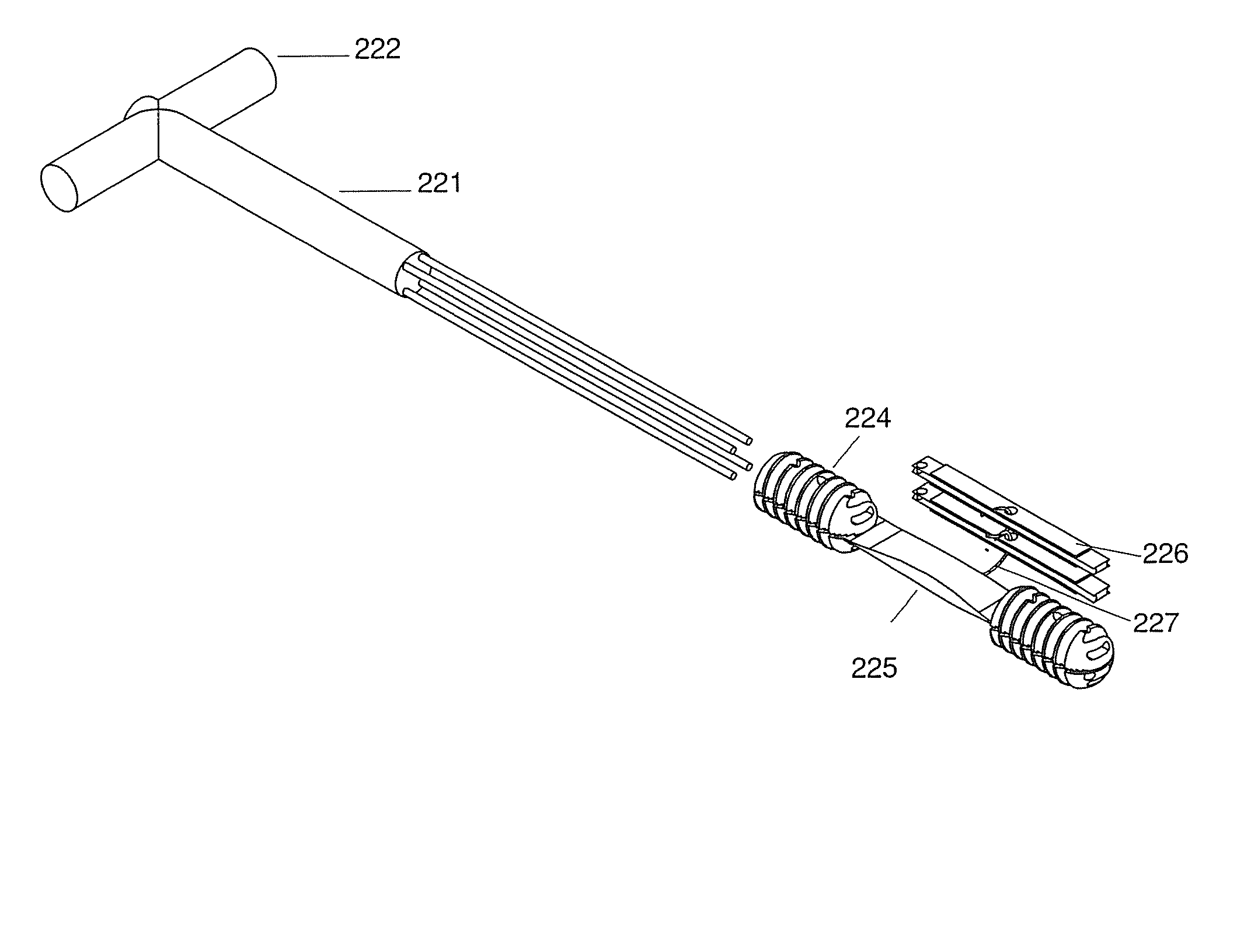
[0174] With the knee in approximately 90 degrees of flexion an incision approximately 2 cm in length is made medial to and just below the tibial tuberosity. The soft tissue is retracted and a small diameter guide pin is driven through the incision proximally to exit through the natural insertion point of the ACL on the tibial plateau. Typically the guide pin is then utilized to direct larger drills along its course sequentially increasing the size of the tibial tunnel. The guide pin is then introduced into the tibial tunnel to pass though the intra-articular space to a point deep in the posterior portion of the intra-condylar notch at the point of the origin of the natural ACL. The guide pin is then driven into the metaphyisis of t...


PUM


Abstract

The present invention has multiple aspects relating to assembled self fixing bone-tendon-bone (BTB) grafts and BTB implants. A preferred application in which self fixing assembled bone-tendon-bone (BTB) grafts and implants of the present technology can be used is for ACL repairs in a human patient. In one embodiment, a self fixing BTB graft is characterized by the presence of threads along at least a portion of the exterior surface of one or both bone blocks. In another embodiment, a self fixing assembled bone-tendon-bone implant comprises a removable tendon tensioner which imparts a predetermined tension on the tendon of the BTB graft. In this embodiment, the tensioner can be narrower than the diameter of the bone blocks or can be threaded such that the threads are continuous with the threads of at least one of the bone blocks. The threads facilitate the simultaneous implantation of the leading and trailing bone blocks of the BTB graft in tapped (threaded) holes in the tibia and the femur of a recipient patient. The tensioner maintains the tension on the tendon and the spacing between the bone blocks until the leading bone block is fixed (threaded) in the tapped hole in the femur and the trailing bone block is fixed (threaded) into the tapped tibial bone tunnel. Once the bone blocks are substantially in their fixed positions, the tensioner is removed arthroscopically in the joint space between the tibia and the femur.

Description

[0001] This application is a continuation-in-part of commonly assigned U.S. Ser. No. 11 / 073,400, filed Mar. 4, 2005, now pending; and a CIP of U.S. Ser. No. 11 / 073,202, filed Mar. 4, 2005, now pending; and a CIP of U.S. Ser. No. 11 / 073,281, filed Mar. 4, 2005, now pending; and a CIP of U.S. Ser. No. 11 / 313,280, filed Dec. 19, 2005, now pending, all of which are incorporated herein by reference.FIELD OF THE INVENTION [0002] The present invention is related to the field of bone-tendon-bone implants, grafts and components thereof, for implantation in mammals, particularly for implantation in humans. In at least one aspect, the present invention is related to a self fixing bone-tendon-bone (BTB) graft comprising a length of tendon or ligament (collectively “tendon”) having a first opposing end and a second opposing end, wherein a first bone block is attached to said first opposing end of said tendon and a second bone block is attached to said second opposing end of said tendon, and wher...

Claims


Application Information

Patent Timeline
IPC IPC(8): A61F2/08
CPCA61F2/0805A61F2/0811A61F2002/0882A61F2002/0841A61F2002/0864A61F2002/0829
Inventor OLSEN, RAYMOND E.LEWIS, WESLEY I.BIANCHI, JOHN R.KUTSAVAGE, JOEURBANIAK, DANIEL J.CARR, ANGELASANDERS, BEN R.
Owner RTI BIOLOGICS INC
Why Eureka
Try Eureka