Total knee implant

a knee joint and implant technology, applied in the field of orthopaedic prostheses, can solve the problems of decreased support and stability of the patient's knee joint, limited external rotation of the femoral component against the tibial component, and failure of ligaments, so as to increase the ability of the surgeon to accurately replicate the natural articulation of the knee joint for a particular patient, the effect of increasing the ability of the surgeon to replicate the natural articulation

Active Publication Date: 2010-07-29
ZIMMER INC
View PDF19 Cites 209 Cited by
  • Summary
  • Abstract
  • Description
  • Claims
  • Application Information

AI Technical Summary

Benefits of technology

[0012]Additionally, by allowing for the use of prosthetic ligaments, the ability of a surgeon to replicate the natural articulation of a knee joint for a particular patient is increased. For example, when a plurality of attachment sites are provided on the tibial and/or femoral components, the surgeon may individually select attachment sites based on specific physical characteristics of an individual patient. As a result, the surgeon may more accurately replicate the natural knee articulation for an individual patient. Further, by providing provisional prosthetic ligaments that allow for separation and/or failure of the provisional prosthetic ligaments if a tension that exceeds a predetermined tension is applied to the provisional prosthetic ligaments, the surgeon may also test the knee joint to determine whether the joint is too tight. The provisional prosthetic ligaments provide a visual and/or tactile feedback that immediately indicates whether the joint is too tight.
[0013]In one form thereof, the present invention provides a prosthetic knee system including a femoral component having a lateral condyle and a medial condyle and a tibial component having a base plate, a medial bearing surface and a lateral bearing surface. The baseplate includes a bone faci...

Problems solved by technology

In a fixed bearing tibial prosthesis, external rotation of the femoral component against the tibial component can be limited due to the fixed nature of the prosthesis.
This may result, for example, in decreased support and stability in the patient...

Method used


Image

  • Total knee implant
  • Total knee implant
  • Total knee implant

Examples


Embodiment Construction

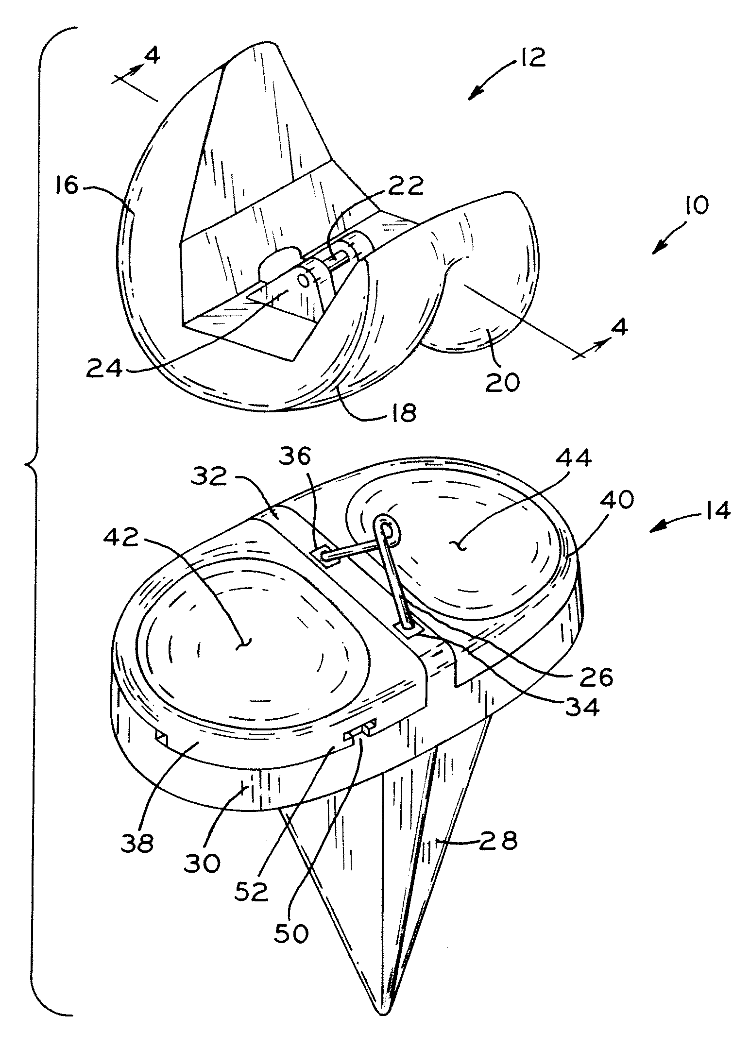
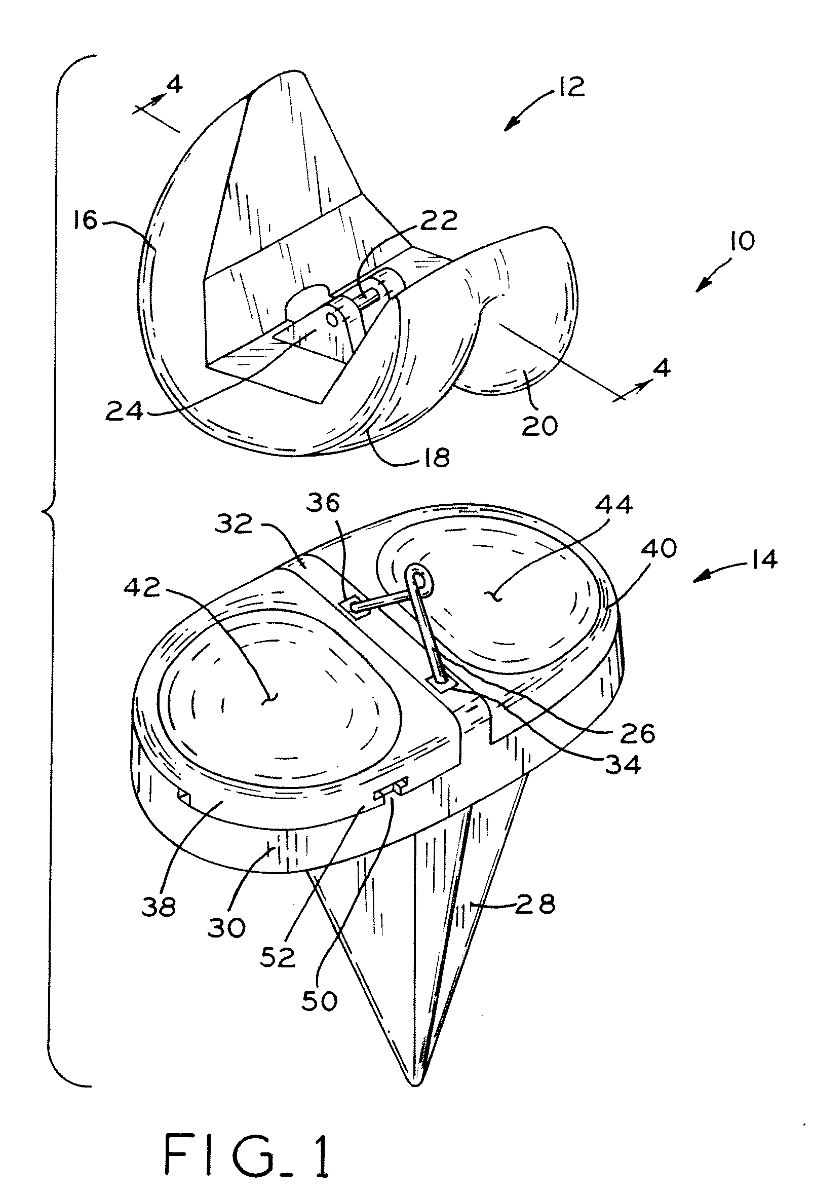
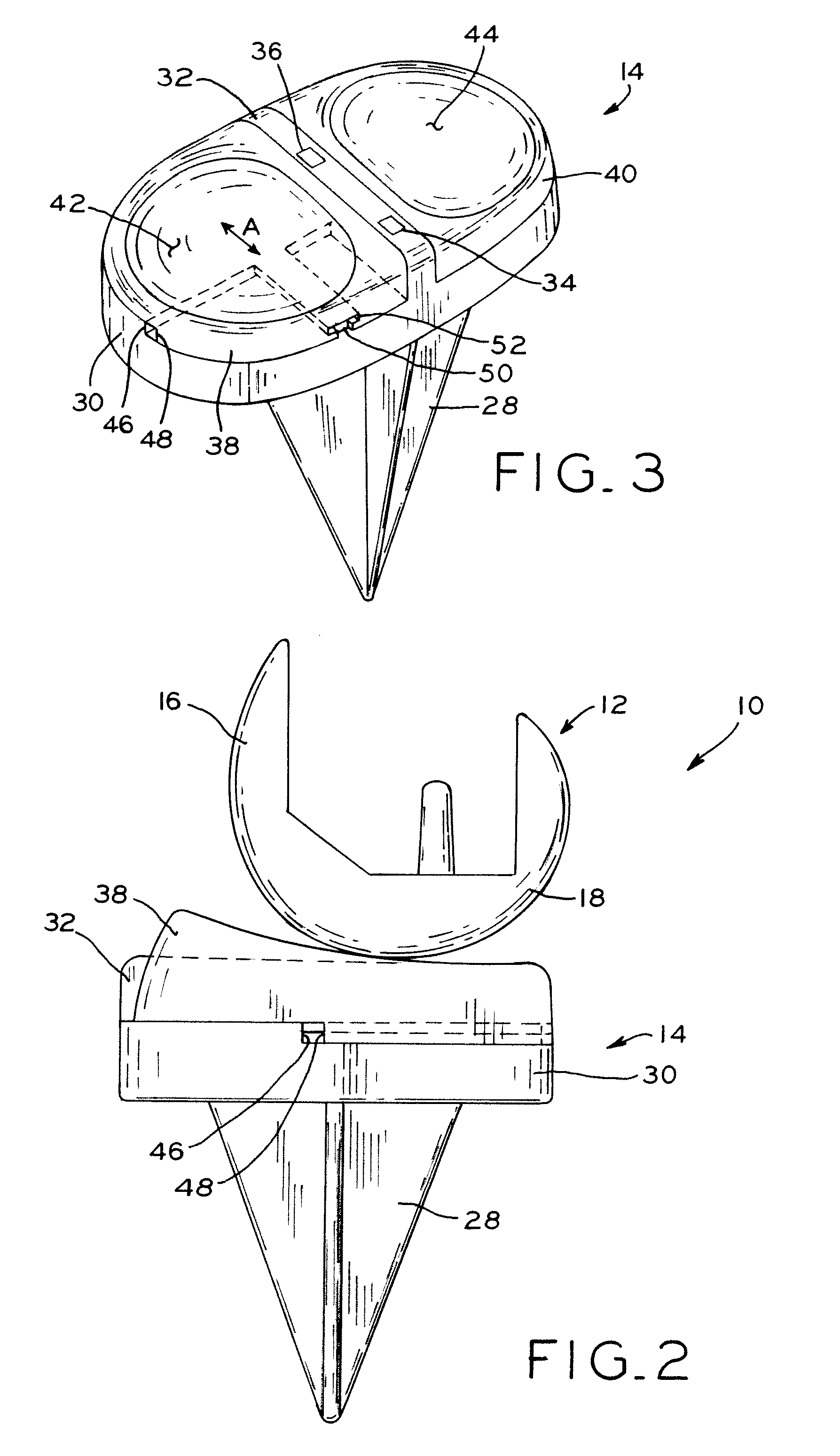
[0036]Referring to FIG. 1, total knee arthroplasty system 10 is shown including femoral component 12 and tibial component 14. Femoral component 12 includes anterior flange 16 and opposing condyles 18, 20, that extend from anterior flange 16. As shown in FIG. 1, total knee arthroplasty system 10 is configured for use in a left knee and, as such, condyle 18 is a lateral condyle and condyle 20 is a medial condyle. However, the principles of the present disclosure are equally applicable to a right or left knee. Extending between opposing condyles 18, 20 is crossbar 22. Crossbar 22 is secured to opposing condyles 18, 20 by base 24 and is designed to receive prosthetic ligament 26 therearound, as defined in detail below. Crossbar 22 may also be integrally formed in base 24, for example.

[0037]Tibial component 14 includes stem or keel 28 connected to baseplate 30. Tibial component 14 is configured for securement to a resected proximal tibia, such that stem or keel 28 is received within the ...


PUM


Abstract

A knee prosthesis is provided for use in knee arthroplasty. In one exemplary embodiment, the present invention provides a tibial prosthesis having a tibial baseplate with a fixed medial bearing component and a mobile lateral bearing component. In one exemplary embodiment, the lateral bearing component is secured to the lateral portion of the tibial baseplate utilizing at least one prosthetic ligament. Additionally, in one exemplary embodiment, a stop is provided to limit anterior or posterior movement of the lateral bearing component relative to the tibial baseplate. For example, the stop may be defined by cooperating shoulders formed on the lateral bearing and the tibial baseplate.

Description

CROSS REFERENCE TO RELATED APPLICATION[0001]This application claims the benefit under Title 35, U.S.C. §119(e) of U.S. Provisional Patent Application Ser. No. 61 / 147,492, entitled TOTAL KNEE IMPLANT, filed on Jan. 27, 2009, the entire disclosure of which is expressly incorporated herein by reference.BACKGROUND[0002]1. Field of the Invention[0003]The present invention relates to orthopedic prostheses and, particularly, to knee prostheses.[0004]2. Description of the Related Art[0005]In a natural knee joint, the meniscus is positioned between the distal end of the femur and the proximal end of the tibia to provide cushioning and support to the tibia and femur as they rotate relative to one another. Additionally, the medial side of the meniscus is more stationary than the lateral side of the meniscus, which is more flexible and / or mobile. The mobility of the lateral meniscus increases the ability of the lateral condyle of the femur to roll off of the tibial plateau during high flexion o...

Claims


Application Information

Patent Timeline
IPC IPC(8): A61F2/38
CPCA61F2/08A61F2250/0073A61F2/3868A61F2/468A61F2/4684A61F2002/30014A61F2002/30387A61F2002/304A61F2002/30462A61F2002/30466A61F2002/3895A61F2002/4666A61F2220/0025A61F2220/0075A61F2250/0018A61F2/385A61F2250/006A61F2/3836
Inventor BYRD, CHRISTOPHER M.SANFORD, ADAM H.EARL, BRIAN D.CLAYPOOL, JODY L.BROWN, JEFFREY D.PENDLETON, JOHN E.
Owner ZIMMER INC
Why Eureka
Try Eureka