Heat insulator

a technology of heat insulation and insulating plate, which is applied in the field of heat insulation plate, can solve the problems of significant environmental burden upon manufacture or disposal, incomplete burning of remaining carbon that cannot react with oxygen, and generation of smoke during incineration, and achieves the effect of convenient installation in the installation position

Active Publication Date: 2013-04-09
KANKYOKEIEISOGOKENKYUSHO CO INC
View PDF13 Cites 1 Cited by
  • Summary
  • Abstract
  • Description
  • Claims
  • Application Information

AI Technical Summary

Benefits of technology

[0014]The present invention has an object of providing a heat insulator that generates no smoke when incinerated, has a low calorific value, and achieves a desired dimension and heat insulation performance.
[0029]Since the sheet member has the protrusions that protrude outward from the upper edges of the pair of side surfaces of the heat insulator, the heat insulator can be installed in the installation position using the protrusions. According to this structure, a heat insulator easily installable in an installation position can be provided.

Problems solved by technology

The heat insulator disclosed in above-mentioned Patent Document 1 is a plastic-based heat insulator, which has a significant environmental burden upon manufacture or disposal.
Accordingly, remaining carbon that cannot react with oxygen burns incompletely and becomes soot, causing generation of smoke during incineration.
Moreover, these heat insulators are made fire-retardant by mixing a fire-retardant material into raw materials, which causes emission of toxic gas when burned.
This raises a possibility of damage by toxic gas in the case of fire.
Furthermore, since these heat insulators are high in calorific value, there is a possibility that an incinerator is damaged upon disposal.

Method used


Image

  • Heat insulator
  • Heat insulator
  • Heat insulator

Examples


Embodiment Construction

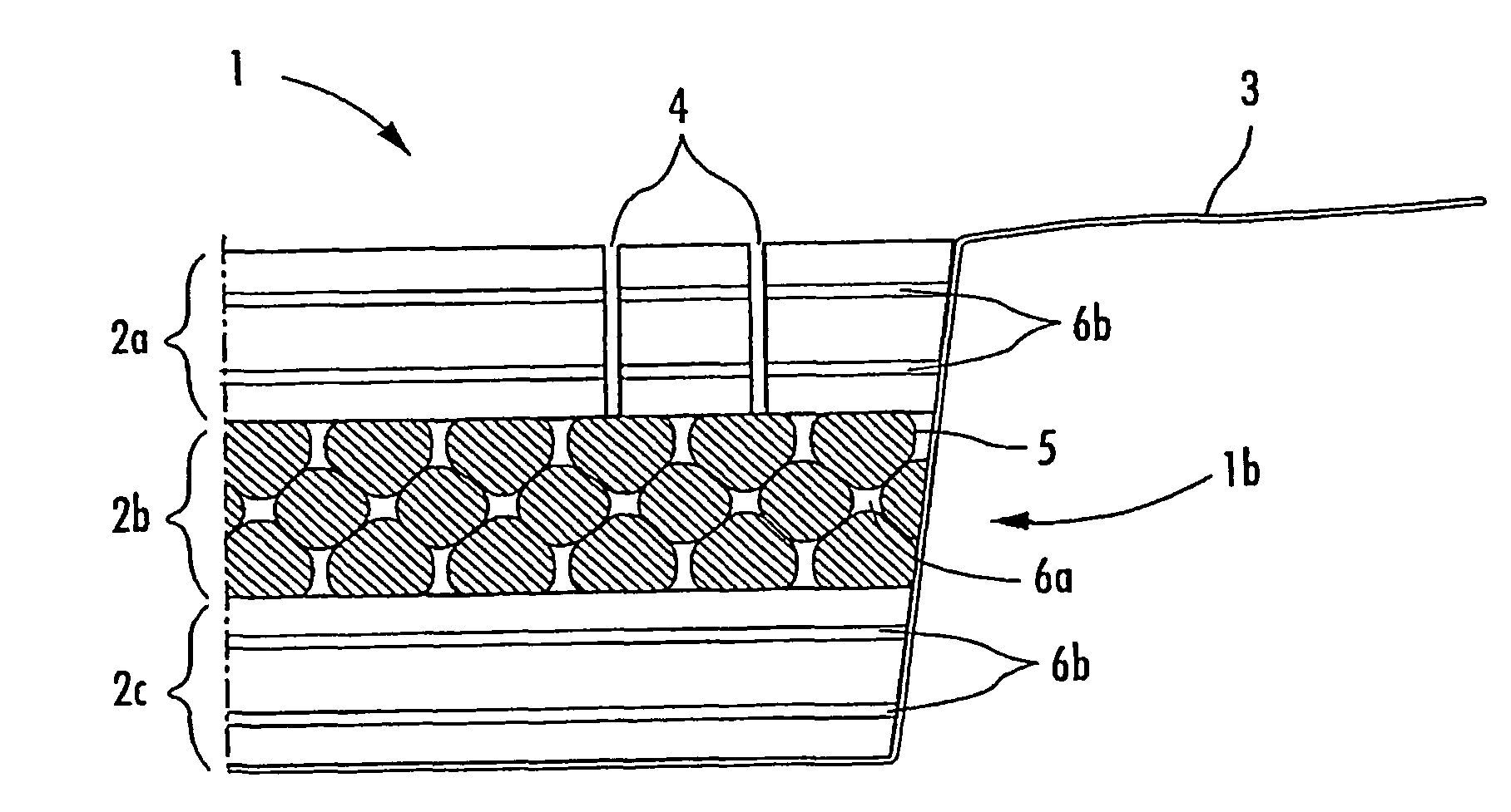
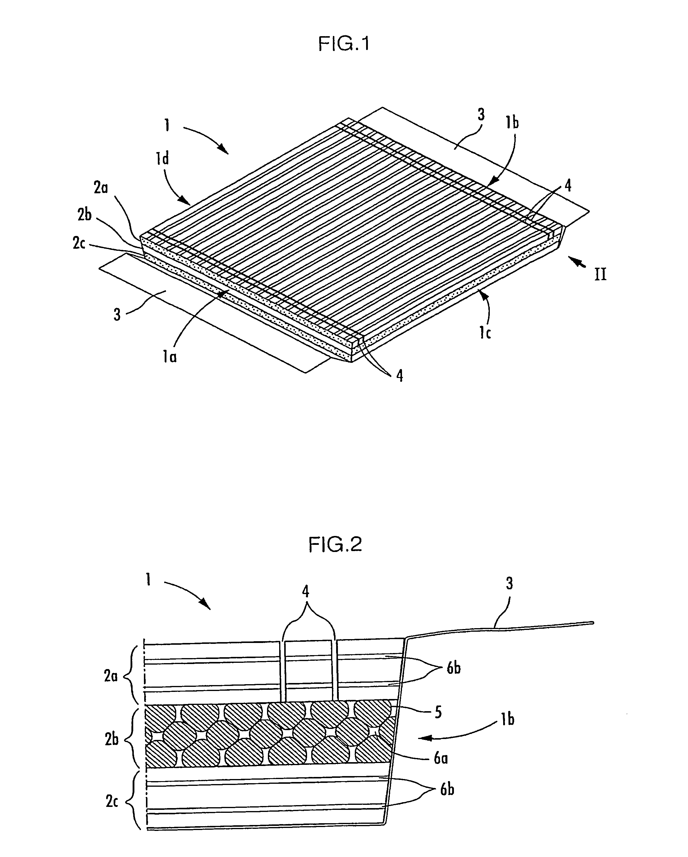
[0037]The following describes a heat insulator according to the present invention, with reference to FIGS. 1 to 6.

[0038]A heat insulator 1 in an embodiment of the present invention is a heat insulator for residential underfloor heat insulation. As shown in FIGS. 1 and 2, the heat insulator 1 is formed by overlaying three plate-like foamed products 2 that are extrusion-molded. A bottom surface and a pair of side surfaces of the heat insulator 1 are covered with a sheet member 3. Note that FIG. 1 shows a state where the sheet member 3 is separated from a side surface 1a in the front, to reveal the structure of the heat insulator 1.

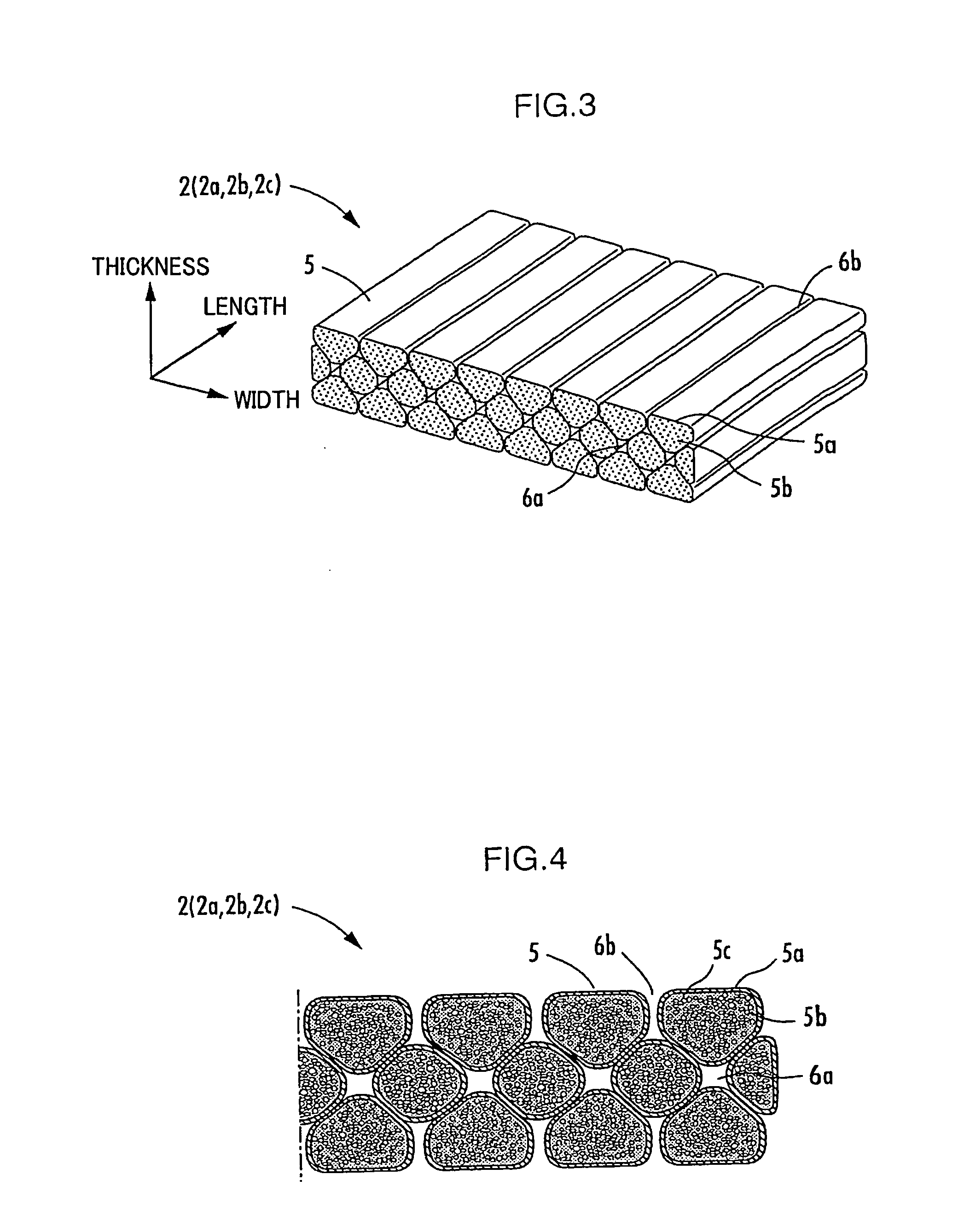
[0039]In the heat insulator 1 in this embodiment, the three plate-like foamed products 2 (2a to 2c) are overlaid so that their extrusion directions are mutually orthogonal, as shown in FIGS. 1 and 2. A vinyl chloride adhesive is applied to an entire contact surface of each of the plate-like foamed products 2a, 2b, and 2c to bond the plate-like foamed product...


PUM

PropertyMeasurementUnit
particle diameteraaaaaaaaaa
calorific valueaaaaaaaaaa
particle diameteraaaaaaaaaa

Abstract

A heat insulator that generates no smoke when incinerated, has a low calorific value, and achieves a desired dimension and heat insulation performance is provided. A heat insulator 1 is formed by heat-mixing, in an extruder 11, a paper pellet 7 that is a mixture of a fine paper powder having a particle diameter of 30 to 200 μm and starch, a container recycle pellet 8 that is a mixture of polypropylene, polyethylene, and polystyrene, foamable polypropylene 9, and water 10 to obtain a plate-like foamed product 2, and orthogonally overlaying a plurality of plate-like foamed products 2. A weight distribution is set so that the paper pellet 7 is 50 to 65% by weight, the container recycle pellet 8 is 13 to 25% by weight, the foamable polypropylene 9 is 10 to 30% by weight, and the water 10 is 10 to 20% by weight to these resins and other materials.

Description

BACKGROUND OF THE INVENTION[0001]1. Field of the Invention[0002]The present invention relates to a heat insulator used for a residential floor and the like.[0003]2. Description of the Related Art[0004]Heat insulators made of various types of materials are used today. For example, as a heat insulator for residential heat insulation, a mineral-based heat insulator such as glass wool or rock wool, a plastic-based heat insulator such as rigid urethane foam or extruded polystyrene foam, or a heat insulator using a natural ingredient such as cellulose fibers or carbonized foam cork is put to use.[0005]Patent Document 1 listed below discloses, as a residential heat insulator, a plate-like heat insulator that is fit between support members such as floor joists, pillars, and ceiling joists and composed of a foamed styrene resin molding or a rigid polyurethane foam.[0006][Patent Document 1] Japanese Patent Application Laid-Open No. H08-74345[0007][Patent Document 2] Japanese Patent Applicatio...

Claims


Application Information

Patent Timeline
Patent Type & Authority Patents(United States)
IPC IPC(8): B32B3/24B32B5/18
CPCB29B17/0042B29C44/468C08J9/0061C08L1/00C08L23/04C08L23/10B29C44/22E04B1/80Y10T428/24314B29K2003/00B29K2023/06B29K2023/12B29K2025/00B29K2105/04B29K2711/12B29L2031/712B29L2031/732C08J2323/04C08J2323/10C08J2325/04C08J2497/00E04B1/806Y10T428/24074Y10T428/24496Y10T428/24504Y10T428/24802Y10T428/24744E04B2001/746C08L2666/02Y10T428/249953Y02W30/62C08J9/12
Inventor MATSUSHITA, TAKAMICHI
Owner KANKYOKEIEISOGOKENKYUSHO CO INC
Why Eureka
Try Eureka