Reflector, an antenna using a reflector and a manufacturing method for a reflector

a manufacturing method and reflector technology, applied in the direction of antennas, antenna details, antenna earthings, etc., can solve the problems of heavy weight and bulky extruded profiles, and achieve the effects of less bulky and lighter

Active Publication Date: 2013-04-09
INTEL CORP
View PDF24 Cites 8 Cited by
  • Summary
  • Abstract
  • Description
  • Claims
  • Application Information

AI Technical Summary

Benefits of technology

[0003]An object with the present invention is to provide a reflector, and an antenna, that is less bulky and lighter than prior art reflectors.
[0004]Another object with the invention is to provide a method for manufacturing a reflector that will produce a reflector that is less bulky and lighter than prior art reflectors.
[0005]An advantage with the present invention is that a complex reflector may be manufactured at a very low cost.
[0006]A further advantage is that the reflector is much lighter than corresponding reflectors according to prior art.
[0007]Still a further advantage is that the physical properties of the reflector are considerable smaller than a reflector that is manufactured using prior art techniques.

Problems solved by technology

For the lower frequencies used in mobile communications (400-1000 MHz) these extruded profiles tends to be very bulky and heavy.

Method used


Image

  • Reflector, an antenna using a reflector and a manufacturing method for a reflector
  • Reflector, an antenna using a reflector and a manufacturing method for a reflector
  • Reflector, an antenna using a reflector and a manufacturing method for a reflector

Examples


first embodiment

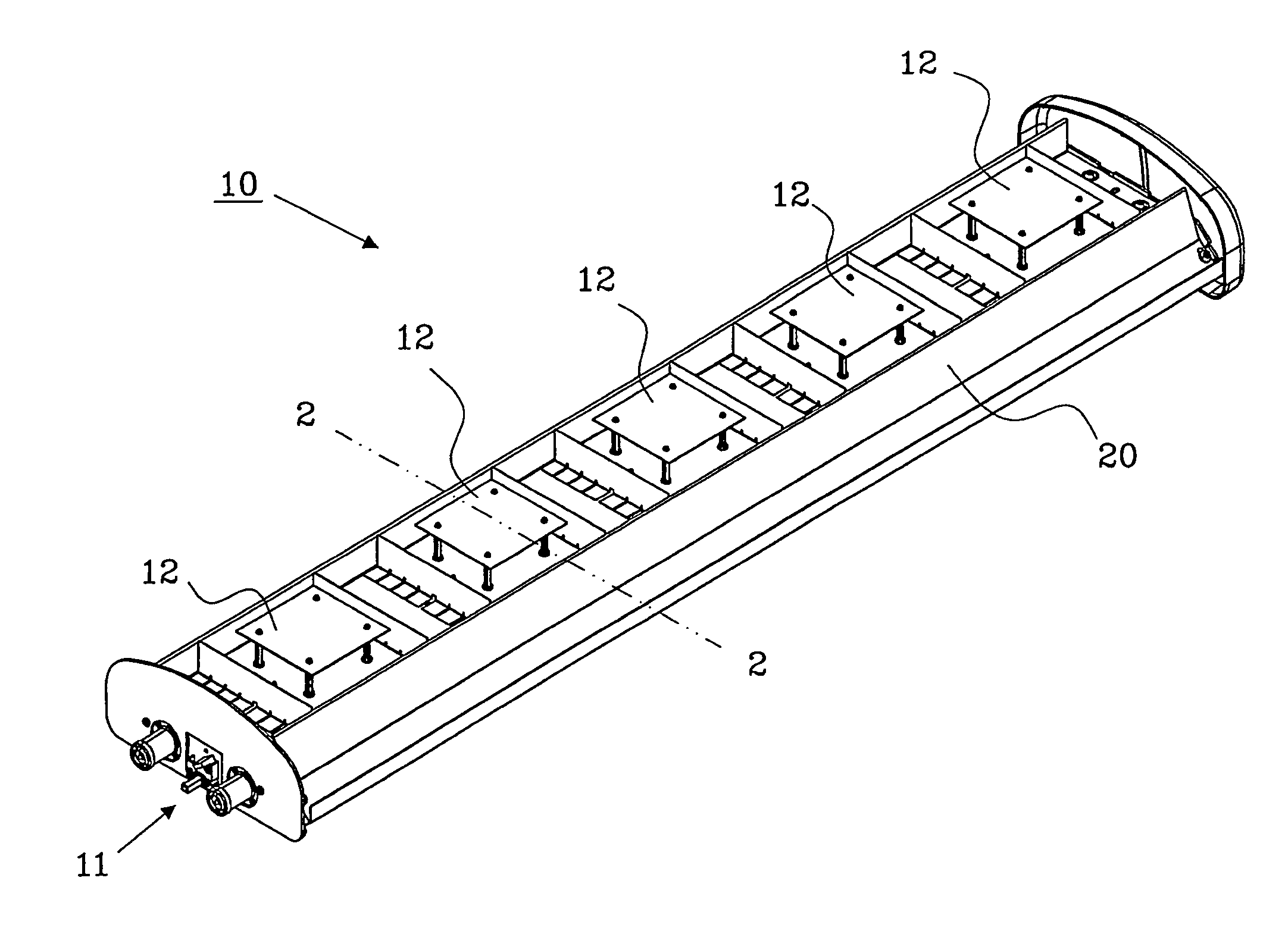
[0014]FIG. 1 shows a perspective view of an antenna 10, preferably used for mobile communication, with a reflector 20 according to the present invention. The antenna comprises input / output connections 11, for feeding signals to / from the antenna 20, antenna elements 12, for transmitting and receiving RF signals in different frequency bands, a distribution network (not shown), such as a phase-shifter, for distributing signals between the input / output connections 11 and respective antenna element 12, and a casing (not shown), mainly for protecting the antenna elements from the environment.

[0015]The antenna 10 comprises five antenna elements 12, but may comprise of fewer, or more, than that, e.g. only one antenna element is possible. In that case a distribution network is not necessary to distribute the signals within the antenna 10.

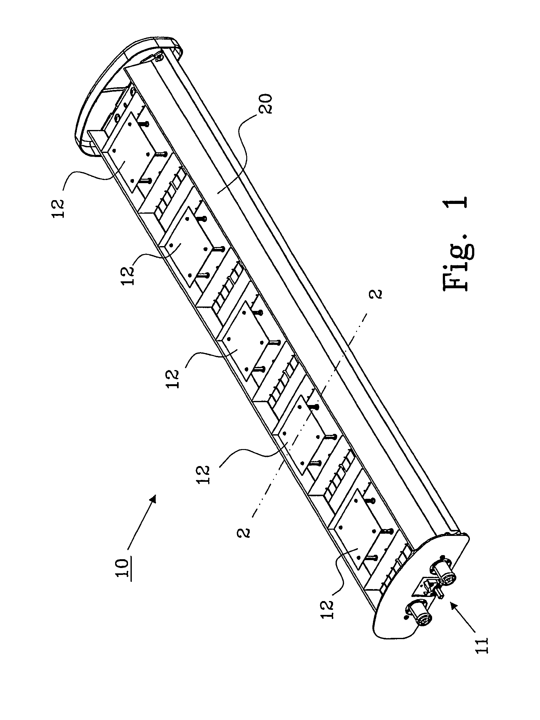
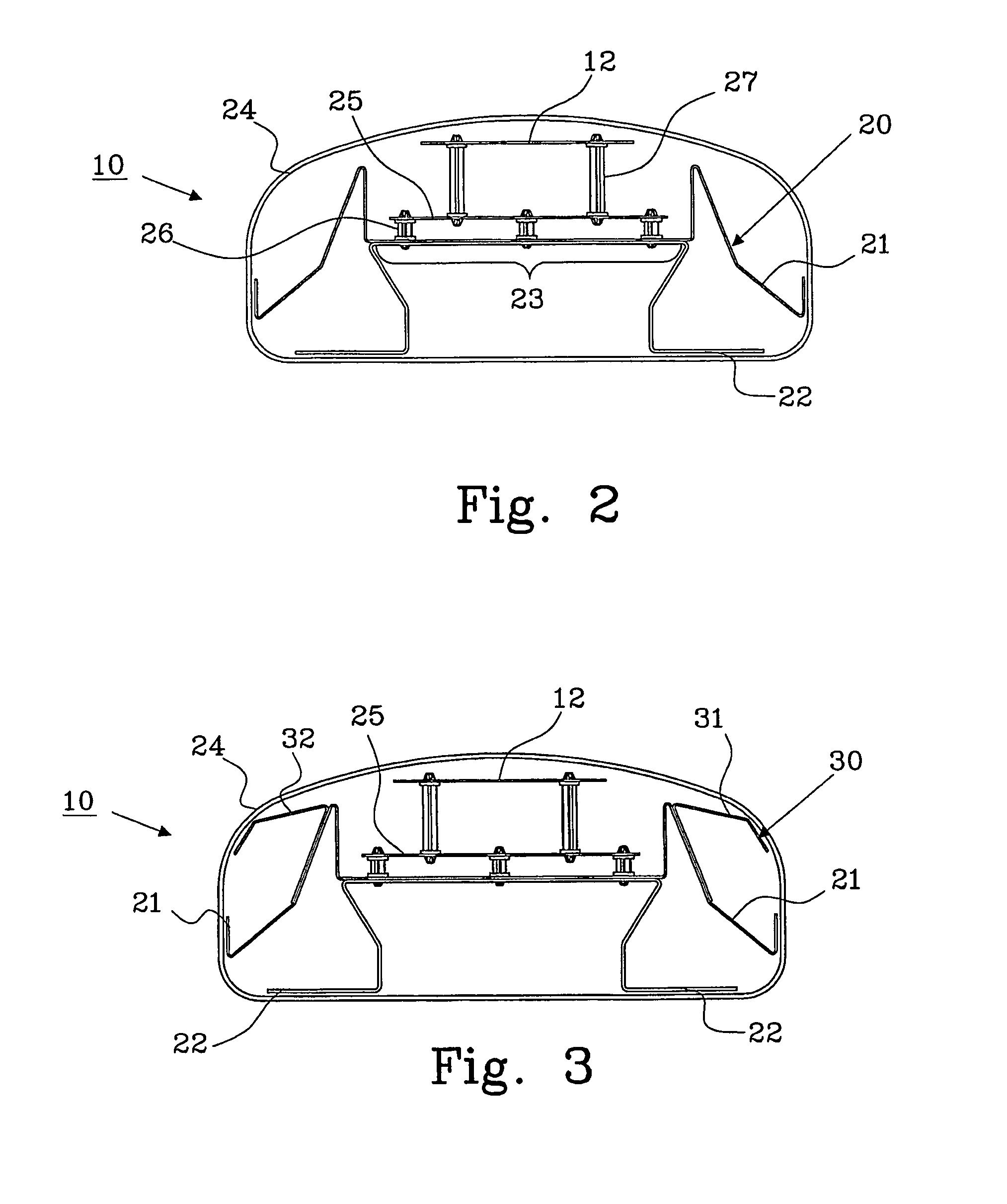
[0016]FIG. 2 shows a cross-sectional view of the antenna 10 in FIG. 1 along line 2-2. The reflector 20 of the antenna 10 comprises, in this first embodiment...

second embodiment

[0019]FIG. 3 shows a cross-sectional view of an antenna 10 with a reflector 30 according the present invention. The reflector 30 comprises a first part 21 and a second part 22, as described in connection with FIG. 2, a third part 31, which is electrically coupled to one side of the first part 21, and a fourth part 32, which is electrically coupled to a second side of the first part 21.

[0020]The antenna element 12 is arranged to the reflector 30 in a similar way as described in connection with FIG. 2, and a casing 24 is also provided surrounding the essential parts.

[0021]The third part 31 and fourth part 32 of the reflector 30 is electrically coupled to the first part 21 either indirectly or directly. An indirect coupling, such as a capacitive coupling, can be made by using a non-conductive adhesive, e.g. tape or glue, between the reflector parts 21 and 22. A direct electrical coupling can be achieved by spot welding, anodizing and bolting or by using a conductive adhesive.

third embodiment

[0022]FIG. 4 shows a cross-sectional view of a reflector 40 according to the present invention. The reflector 40 comprises two parts 41 and 42. This reflector is adapted to be mounted in an antenna that has a different loob pattern compared to the reflector described in FIGS. 1-3.

[0023]The loob pattern of the reflector shown in FIG. 4 has a 65 degrees 3 dB beam width and the reflectors shown in FIGS. 1-3 has 90 degrees 3 dB beam width.

[0024]FIG. 5 shows an alternative embodiment of an antenna 50 with the first embodiment of the reflector 20 according to the present invention. The casing of the antenna 50 comprises a base 51 and a cover 52. The second part 22 of the reflector 20 is integrated in the base 51 of the casing, and the first part 21 of the reflector 20 is electrically coupled to the second part 22 when mounting the antenna to its operating position in a communication mast.


PUM


Abstract

The present invention relates to a reflector 20; 30; 40 for use in an antenna 10; 50. The reflector 20; 30; 40 is arranged to be used as an earth plane of the antenna 10 and the reflector is corrugated to form current pockets. The reflector 20; 30; 40 comprises at least two separate parts 21, 22; 21, 22, 31, 32; 41, 42, and the parts are electrically coupled to each other to commonly form the earth plane of the antenna 10; 50. The invention also relates to an antenna including a reflector, and to a method for manufacturing a reflector.

Description

TECHNICAL FIELD[0001]The present invention relates to a reflector of the type defined in the preamble of claim 1. The invention also relates to an antenna using a reflector as defined in the preamble of claim 9 and a manufacturing method for a reflector as defined in the preamble of claim 10.BACKGROUND TO THE INVENTION[0002]Corrugations are well known in the art for shaping of antenna patterns, for example in horn antennas see U.S. Pat. Nos. 3,949,406, 4,295,142, 4,477,816, 4,533,919. Corrugated reflectors are also used in base station antennas for mobile communication. These reflectors are manufactured using extruded profiles with corrugations or current traps, which in function are shorted quarter wavelengths parallel plate wave guides, making one polarization of the currents see a high (infinite) impedance. By using this corrugations / current traps the currents on the reflector can be controlled and thereby the radiated fields of the antenna are controlled. For the lower frequenci...

Claims


Application Information

Patent Timeline
Patent Type & Authority Patents(United States)
IPC IPC(8): H01Q19/10H01QH01Q1/24H01Q1/48H01Q1/52H01Q15/14H01Q15/18
CPCH01Q1/246H01Q1/48H01Q15/18H01Q1/521H01Q15/141H01Q1/52H01Q13/0208
Inventor LINDBERG, CHRISTOFERUDDIN, JESPEREDLUND, JOHANARVIDSSON, PER-ANDERS
Owner INTEL CORP
Why Eureka
Try Eureka