Blow molding system for the manufacture of thermoplastic receptacles

a technology of blow molding and thermoplastic receptacles, which is applied in the field of blow molding system for the manufacture of thermoplastic receptacles, can solve the problems of higher electrical power consumption and more expensive, and achieve the effects of less electrical power to run, less power consumption, and reduced cos

Active Publication Date: 2009-07-21
SIDEL PARTICIPATIONS SAS
View PDF4 Cites 17 Cited by
  • Summary
  • Abstract
  • Description
  • Claims
  • Application Information

AI Technical Summary

Benefits of technology

[0012]In practice, it is advantageous to maintain, as in the earlier systems, pneumatic operation of the movable equipment, by contriving for respective portions of the tubular body and of the movable equipment which face each other to be arranged as an at least single-acting pneumatic actuator for moving the movable equipment along the tubular body in the direction of the mold and holding the nozzle in said sealed communication with the neck of the parison. A result of this is that the nozzle can be kept pressed in a sealed fashion against the neck of the receptacle or against the wall of the mold using a pressure that is appreciably lower than the high pressure of the blow-molding fluid; as for the moving of the movable equipment by the pneumatic actuator, a low pressure driving fluid is sufficient here too. Thus, the movable equipment including the nozzle can be operated (apart from the actual blowing itself) using a relatively low-pressure driving fluid; typically, it will be possible to use compressed air at 7×10⁵ Pa which is commonly available in all industrial facilities.
[0013]The design of a blow-molding system according to the invention leads to a substantial saving in high-pressure fluid which can now be reserved simply for the blow-molding phase. A result of this is that it is possible, in order to produce the high-pressure fluid, to use a compressor of an appreciably lower capacity, which is therefore less expensive to purchase and requires less electrical power to run; furthermore, it is less bulky and its smaller size, together with other modifications made to the remainder of the manufacturing system, lead to designs of manufacturing systems which occupy less floorspace.

Problems solved by technology

Now, from a financial standpoint, producing fluid at high pressure, typically at pressures of 40×105 Pa, represents a very significant item of expenditure in the operation of the entire thermoplastic receptacle (particularly bottle) production line: specifically, the higher the consumption of high-pressure fluid, the more highly specified the compressor needs to be, and therefore the more expensive it is, and furthermore, the higher its electrical power consumption.

Method used


Image

  • Blow molding system for the manufacture of thermoplastic receptacles
  • Blow molding system for the manufacture of thermoplastic receptacles
  • Blow molding system for the manufacture of thermoplastic receptacles

Examples


Embodiment Construction

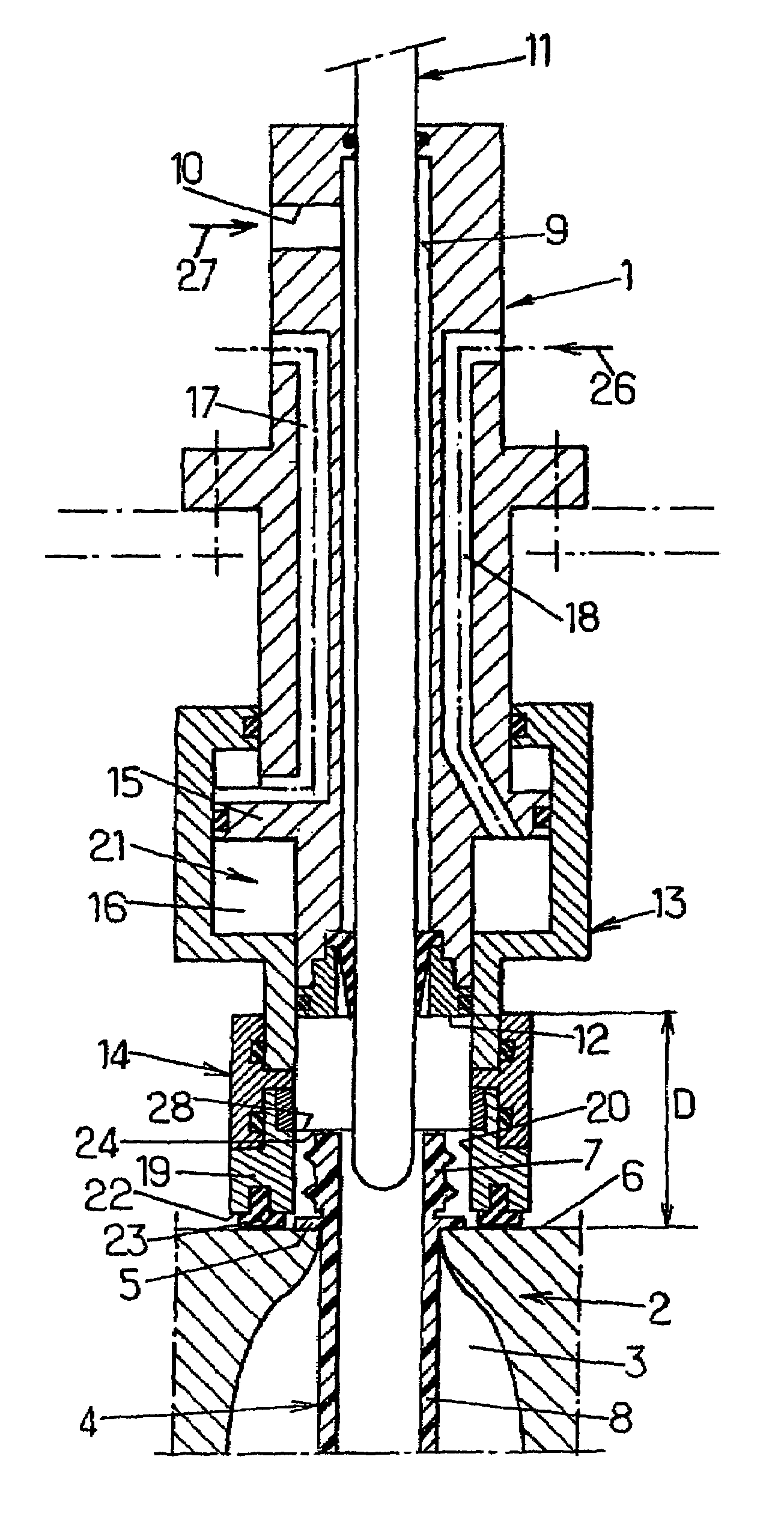
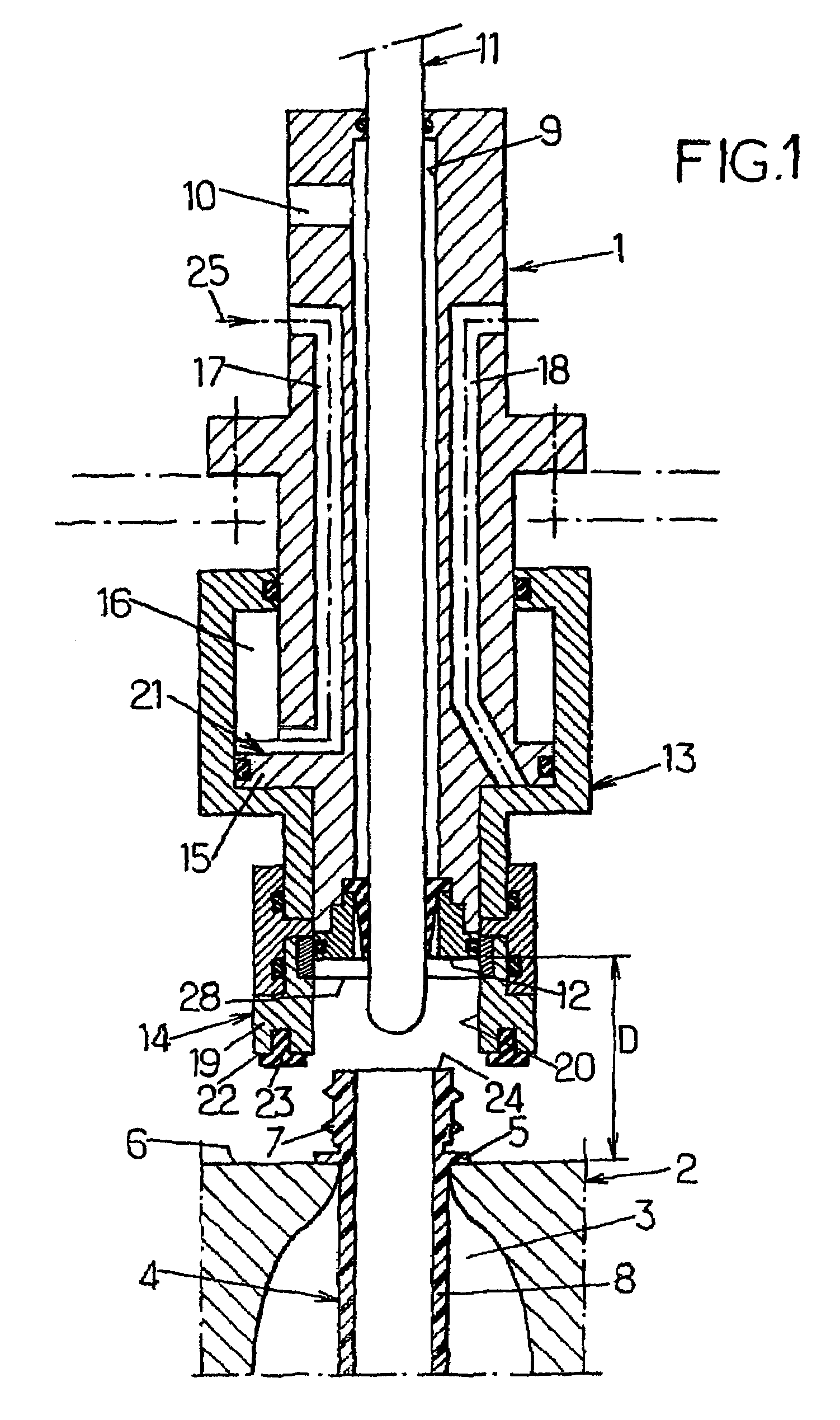
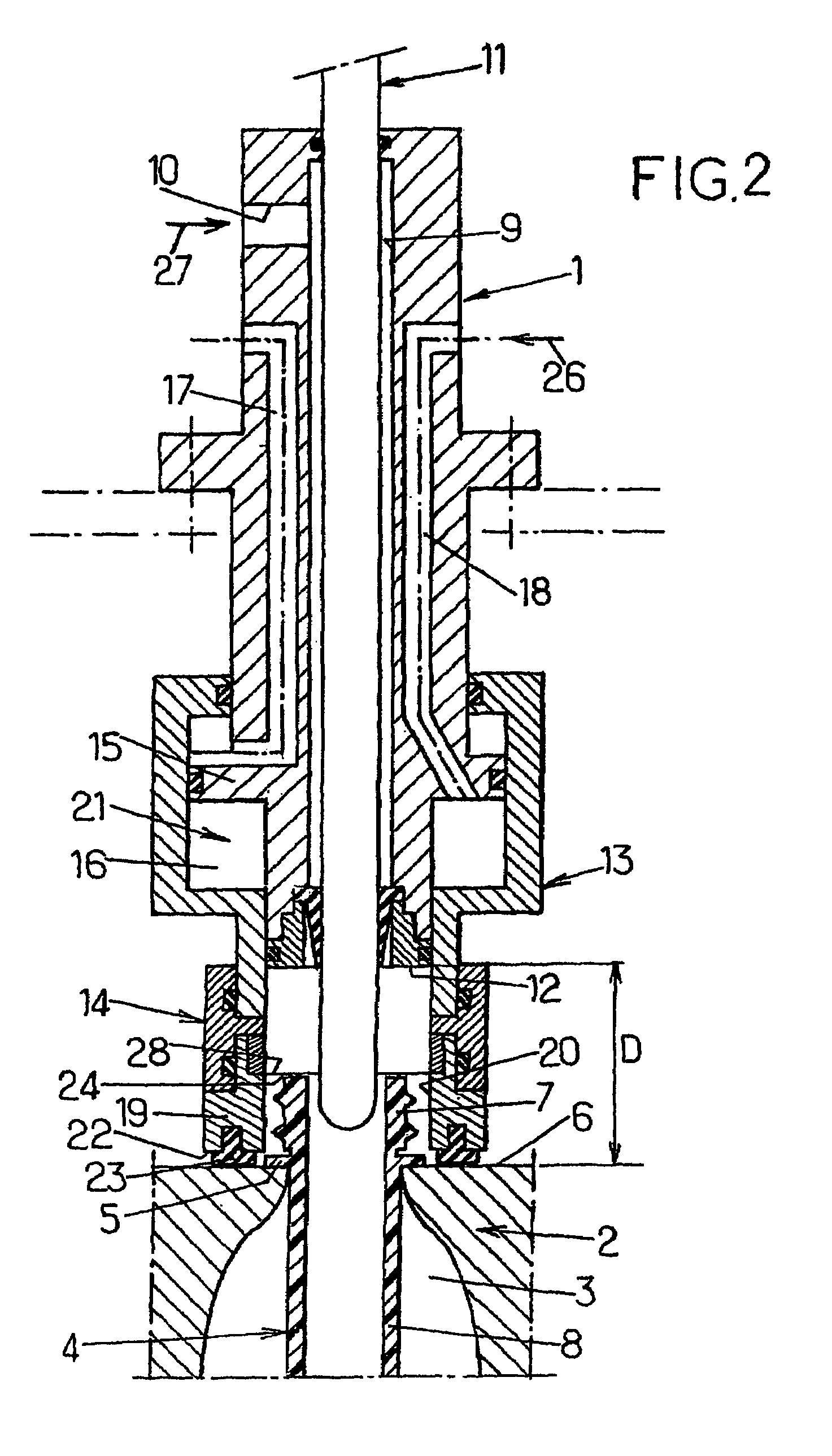
[0021]FIG. 1, to which reference is made first of all, depicts part of a blow-molding system in which only those elements necessary for understanding the invention are depicted.

[0022]The blow-molding system comprises a stationary body 1 supported by a support structure (not depicted) over a mold 2, it too supported in a stationary manner by the same support structure. In practice, this support structure may form part of a revolving structure or carousel combining numerous molds distributed about the circumference and surmounted by respective blow-molding systems. In practice also, the body 1 of the blow-molding system extends more or less vertically above the mold and more or less coaxially with respect to the molding cavity 3 of the mold.

[0023]So as to present a more concrete example, a parison 4 (in this instance a preform) has been shown in position in the mold 2 awaiting blowing. The parison 4 is positioned in such a way that it is supported, via its flange 5, on the wall 6 (top...


PUM

PropertyMeasurementUnit
pressureaaaaaaaaaa
pressuresaaaaaaaaaa
pressureaaaaaaaaaa

Abstract

A blow molding system for a thermoplastic blank which is supported in a mold. The system includes a fixed tubular body connected to a high-pressure fluid source and, at the lower end thereof, supporting moveable equipment consisting of a tuyere, the tuyere being defined laterally by a terminal sleeve of the moveable equipment and the bottom thereof being the front wall of the body, wherein the lateral inner wall of the sleeve is configured in such a way that the pressure of a fluid inside the tuyere does not result in a reaction force component on the lateral wall, which is directed opposite to the wall of the mold.

Description

FIELD OF THE INVENTION[0001]The present invention relates to improvements made to blow-molding systems able to supply a blow-molding fluid at high pressure into a thermoplastic parison which is supported, in a blow-molding mold, by its neck emerging from a wall of the mold, said system comprising a stationary tubular body which is in communication with a source of high-pressure fluid and which, at its lower end, coaxially and slidably supports a movable equipment comprising a blowing nozzle able, in the blowing position, to be placed in sealed communication with the neck of the parison, the nozzle being laterally defined by a terminal part, in the form of a sleeve, of the movable equipment, the tubular body having a transverse face which lies a fixed distance from said wall of the mold.BACKGROUND OF THE INVENTION[0002]Various blow-molding systems of the type in question are known, particularly systems equipped with various types of nozzles either designed to be brought into physical...

Claims


Application Information

Patent Timeline
Patent Type & Authority Patents(United States)
IPC IPC(8): B29C49/58
CPCB29C49/58B29C49/36B29C49/4236B29C2791/006B29C2049/5865B29C2049/5879B29C2049/5882B29C2049/5827B29C2049/7831
Inventor MIE, PATRICK
Owner SIDEL PARTICIPATIONS SAS
Why Eureka
Try Eureka