Digital Dispense System

a digital and dispense technology, applied in the field of analytical instruments, can solve the problems of high-end devices and time-consuming procedures, and achieve the effect of less expensive purchase and easy visualization

Pending Publication Date: 2021-09-09
FUNAI ELECTRIC CO LTD
View PDF1 Cites 0 Cited by
  • Summary
  • Abstract
  • Description
  • Claims
  • Application Information

AI Technical Summary

Benefits of technology

[0004]Well plates, slides and other substrates are used for many experiments and laboratory procedures. The process of filling the wells or spotting is often performed manually or using expensive lab equipment. In some cases, the wells are filled with hand operated pipettes. In other cased, high-end automated devices based on pipette technology are used to fill the well plates. Such automated devices accommodate an open well dispense head only. The open well dispense head is a dispense head where a small amount of fluid must be deposited into an opening in the dispense head before use. The fluid is typically deposited manually using a pipette or similar means. The dispense head is held stationary while moving the microplate in both X and Y directions. These high end devices are extremely expensive. Accordingly, there is a need for a digital dispense system that can be used in a wide variety of analytical situations for analysis and digital titration of samples that is much less expensive to purchase. There is also a need for readily visualizing the volume of fluid in each well of a well tray or the amount of fluid that is applied to a predetermined area of a slide.

Problems solved by technology

When there are a large number of patients that require blood sample analysis, the procedures may be extremely time consuming.
The process of filling the wells or spotting is often performed manually or using expensive lab equipment.
These high end devices are extremely expensive.

Method used


Image

  • Digital Dispense System
  • Digital Dispense System
  • Digital Dispense System

Examples


Embodiment Construction

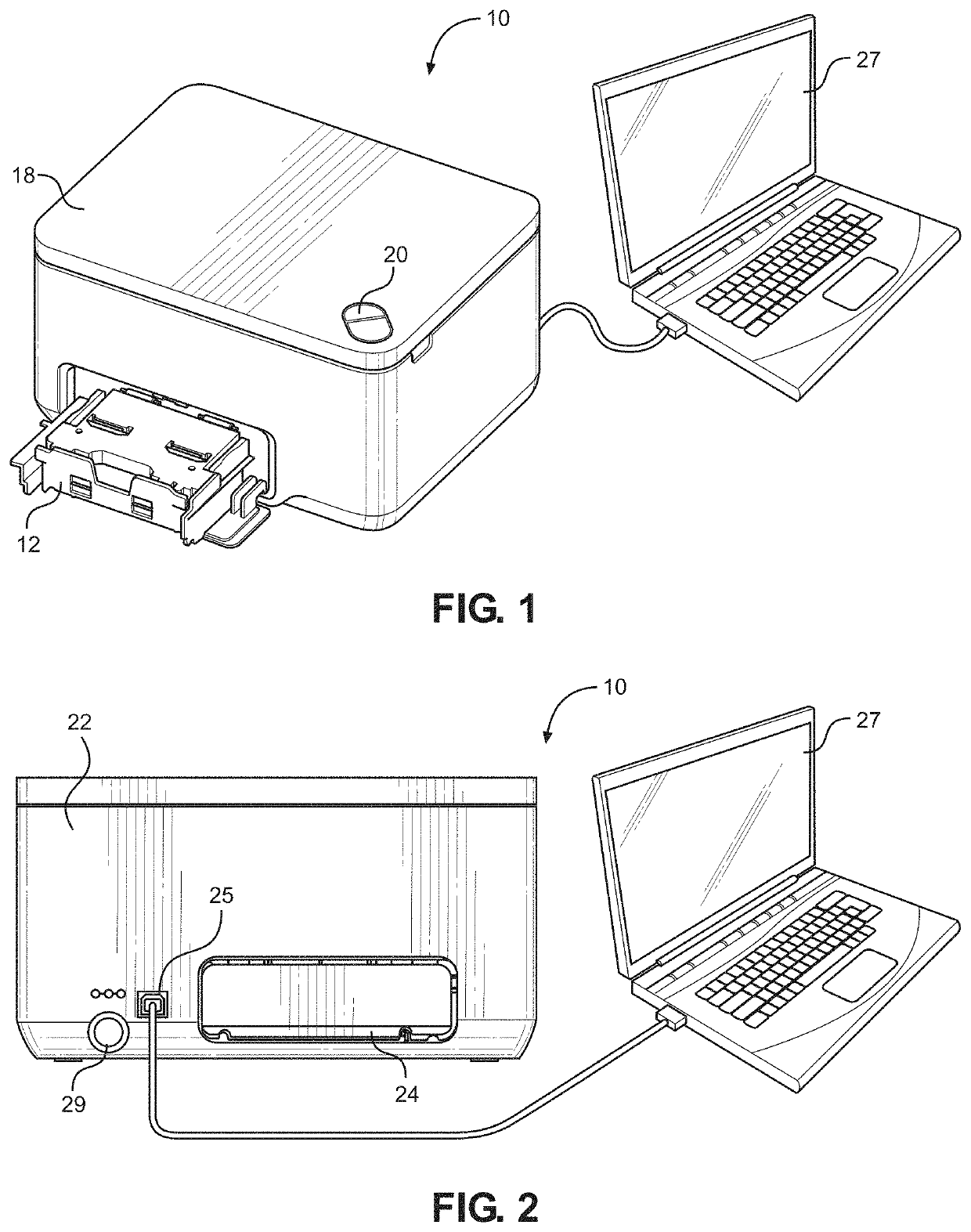
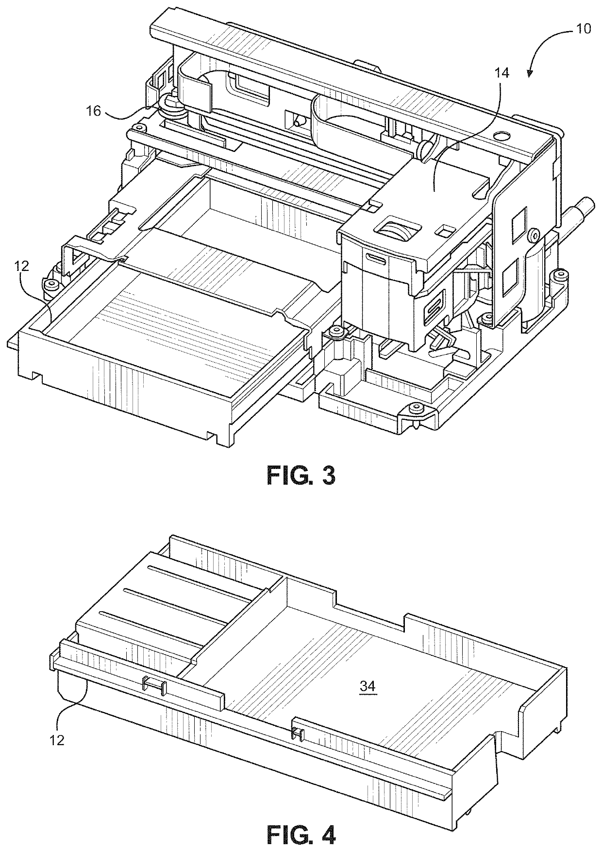
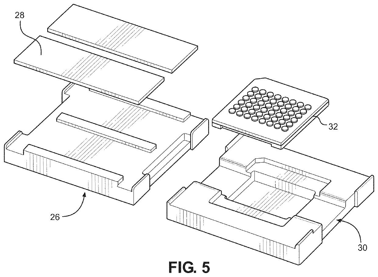
[0022]With reference to FIGS. 1-9 there is shown a digital dispense device 10 for accurately dispensing an amount of one or more fluids into the wells of a well plate, or in some defined pattern of spots on a slide (commonly referred to as spotting). Unlike the high-end digital dispense devices, the device 10 of the present invention is based on an ejection head and fluid cartridge 14 that moves back and forth in a first direction and a tray 12 containing the wells or slides that moves back and forth in a second direction orthogonal to the first direction, as described in more detail below. The disclosed device 10 can accept open and closed dispense heads rather than just open dispense head. The tray 12 is adaptable to both standard micro-well plates as well as glass slides and other substances. The ejection head on the ejection head and fluid cartridge 14 may be selected from a wide variety of ejection head devices including, but not limited to, thermal jet ejection heads, bubble j...


PUM

PropertyMeasurementUnit
volumeaaaaaaaaaa
volumesaaaaaaaaaa
relative volumeaaaaaaaaaa

Abstract

A digital dispense system and method for analyzing samples. The system includes a fluid droplet ejection system housed in a compact housing unit. The fluid droplet ejection system contains a fluid droplet ejection head and fluid cartridge containing one or more fluids to be dispensed, a cartridge translation mechanism for moving the fluid droplet ejection head and fluid cartridge back and forth over a sample holder in an x direction; and a sample holder translation mechanism for moving a sample back and forth beneath the fluid droplet ejection head and fluid cartridge in a y direction orthogonal to the x direction. A digital display device is attached to the fluid droplet ejection system for displaying fluid volume information to a user. The fluid volume information is selected from relative fluid volume, absolute fluid volume, and a combination of relative and absolute fluid volumes.

Description

RELATED APPLICATION[0001]This application claims priority to provisional application Ser. No. 62 / 788,290, filed Jan. 4, 2019, now pending.TECHNICAL FIELD[0002]The disclosure is directed to analytical instruments and in particular to instruments that are used to dispense fluids for analytical purposes.BACKGROUND AND SUMMARY[0003]In the medical field, in particular, there is a need for automated sample preparation and analysis. The analysis may be colorimetric analysis or require the staining of samples to better observe the samples under a microscope. Such analysis may include drug sample analysis, blood sample analysis and the like. In the analysis of blood, for example, blood is analyzed to provide a number of different factors that are used to determine the health of an individual. When there are a large number of patients that require blood sample analysis, the procedures may be extremely time consuming. Also, there is a need for accurate preparation of the samples so that the re...

Claims


Application Information

Patent Timeline
Patent Type & Authority Applications(United States)
IPC IPC(8): G01N1/31G01F11/00
CPCG01N1/312G01F11/006G01N1/31G01N2001/317B41J2/01B41J3/46B41J29/393H01L21/6715G01N35/109G01N2035/1041G01N2035/00138G01N35/1016G01N2035/00891G01N35/00722B01L3/0203B01L3/0265B01L3/0268G01N1/2813G01N35/00029G01N2001/2826G01N2035/00039
Inventor DEBOARD, BRUCE AMARRA, III, MICHAEL A.SHARMA, PRAMOD K.
Owner FUNAI ELECTRIC CO LTD
Why Eureka
Try Eureka