Snap fastener

a technology of snap fasteners and snap clips, which is applied in the field of snap fasteners, can solve the problems of plastic snap fasteners not creating a sufficient retention force in their attachment to fabrics, and the manufacturing of strapped metal snap fasteners is somewhat complex

Inactive Publication Date: 2010-07-13
ORC INDS
View PDF10 Cites 17 Cited by
  • Summary
  • Abstract
  • Description
  • Claims
  • Application Information

AI Technical Summary

Benefits of technology

[0007]The snap fastener of the present invention generally includes a male portion and female portion. The male portion and female portion are joinable to one another via a rivet attached to the male portion which may be passed through a textile item or other material before joining the male portion to the female portion for attachment to the fabric. Thus, each snap has both a male portion and a female portion when assembled. This arrangement has the advantage of presenting a snap that can be closed two different ways, either from the front or from the rear.
[0008]The snap fastener of the present invention also has strategically placed barbs on the back surface of both the male portion and the female portion in order to maximize gripping of the textile material or other material to which the snap is attached. The barbs are placed in such a way that the barbs on the male portion and the barbs on the female portion do not interfere with one another yet interlock when assembled. The snap fastener of the present invention is also formed so that the male portion has on its back surface a raised ridge around the rim of the male portion. This allows the male portion to have a lowered profile when attached to the female portion thus providing a snap that is less bulky.

Problems solved by technology

Stamped metal snap fasteners are somewhat complex to manufacture as each of the two halves of the snap fastener is formed from several parts that must be joined together.
Currently plastic snap fasteners may not create a sufficient retention force in their attachment to fabrics and like materials.

Method used


Image

  • Snap fastener
  • Snap fastener
  • Snap fastener

Examples


Embodiment Construction

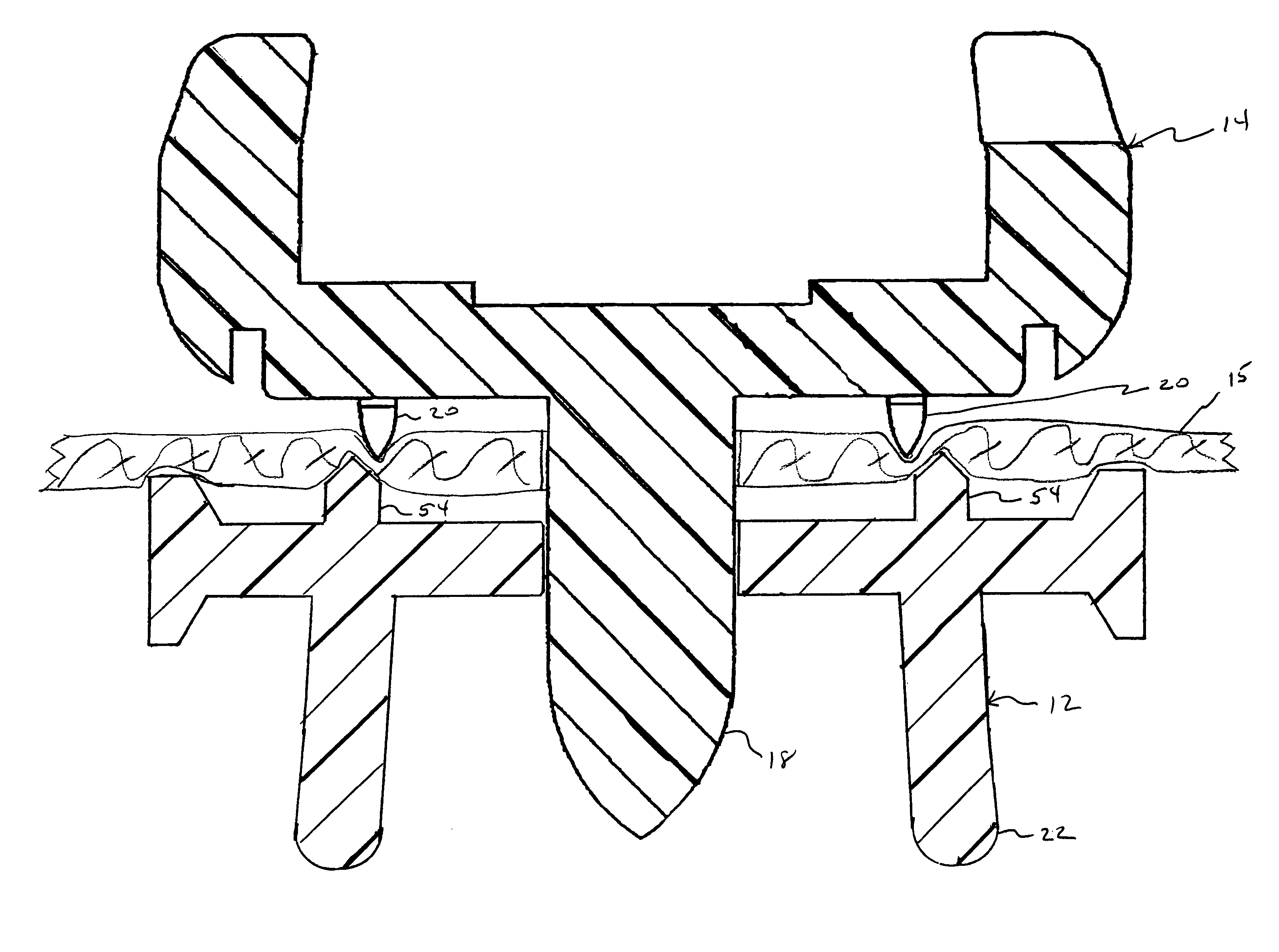
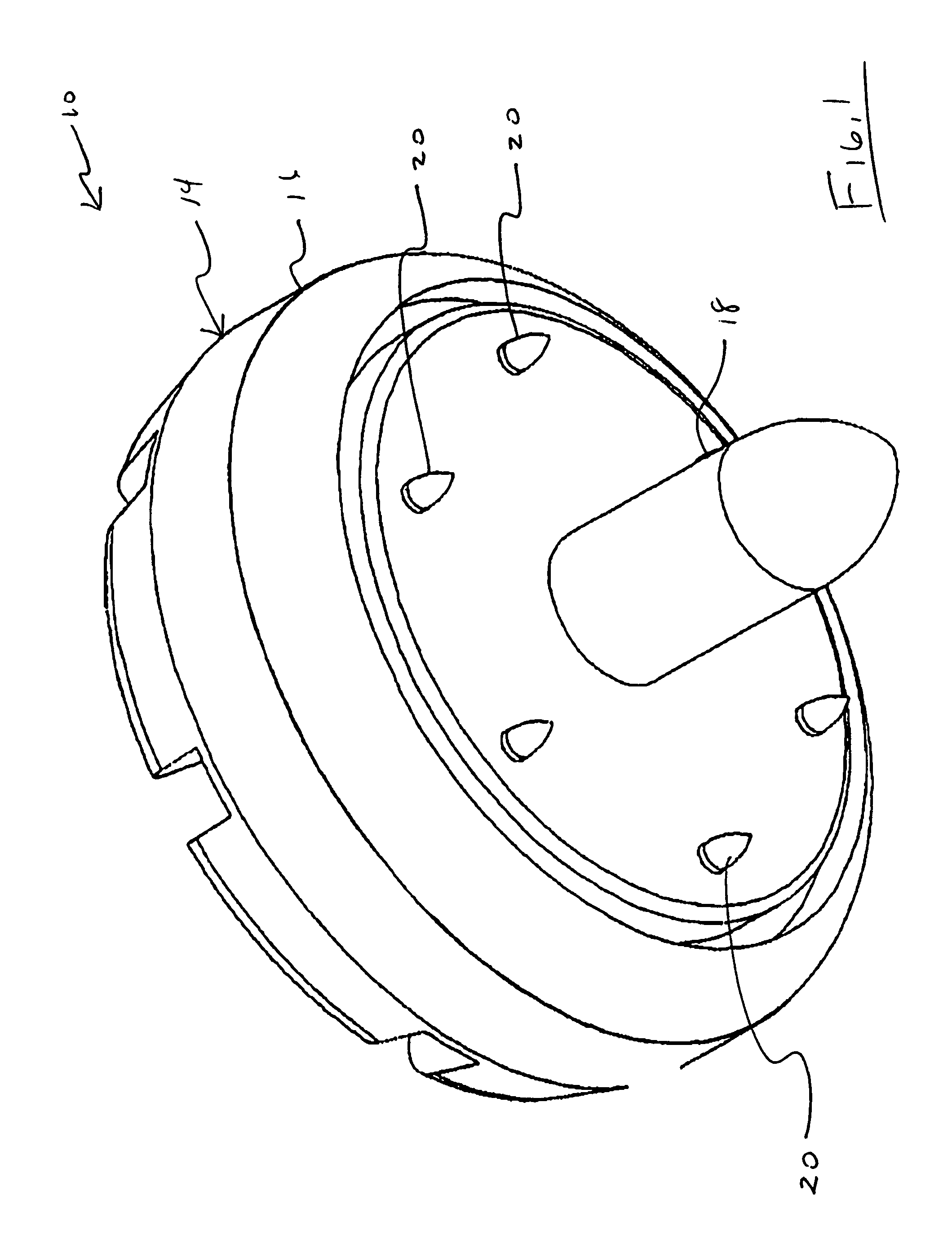
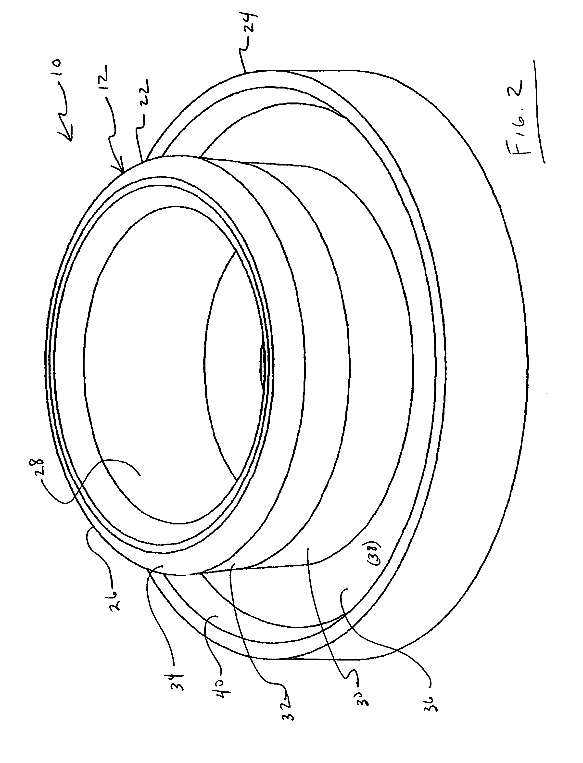
[0021]Referring to FIGS. 1 and 2, snap fastener 10 generally includes female portion 12 and male portion 14. Female portion 12 and male portion 14 are formed from a polymer material. For example, female portion 12 and male portion 14 may be formed from holopolymer plastic, such as Delron or another appropriate polymer. Snap fastener 10 may be advantageously formed by injection molding but may be formed by other techniques as well. Snap fastener 10 may be used for fastening on a textile product 15 but may also be used on various other applications such as attaching fabric covers to solid structures.

[0022]Snap fastener 10 may be secured to a textile product by a mechanical approach that includes peening. This will be discussed further below. Other securing techniques may be used as well.

[0023]Referring to FIG. 1 male portion 14 generally includes cup portion 16, rivet shaft 18 and barbs 20.

[0024]Referring to FIG. 2, female portion 12 generally includes stud 22 and plate 24.

[0025]Refer...


PUM


Abstract

A molded polymer snap fastener, including a first portion having a plurality of first barbs extending outwardly therefrom, the first barbs each having a first radius R1 and the second portion having a plurality of second barbs extending outwardly therefrom, the second barbs having a second radius R2. The first barbs are arranged along a first substantially circular line, the first substantially circular line having a third radius R3. The second barbs are arranged along a second substantially circular line, the second substantially circular line having a fourth radius R4. The third radius R3 is different from the fourth radius R4 and the second barbs and the first barbs are arranged such that the second barbs fall into spaces between the first barbs when the first portion and the second portion are mated.

Description

CLAIM TO PRIORITY[0001]This application claims the benefit of U.S. Provisional Application No. 60 / 727,069, filed Oct. 14, 2005 entitled “SNAP FASTENER.”FIELD OF THE INVENTION[0002]The invention generally relates to snap fastener for fastening clothing and the like. More particularly the invention relates to polymer snap fasteners.BACKGROUND OF THE INVENTION[0003]Snap fasteners have existed for decades. Existing snap fasteners have primarily been formed from stamped metal. Stamped metal snap fasteners are somewhat complex to manufacture as each of the two halves of the snap fastener is formed from several parts that must be joined together.[0004]Snap fasteners generally have a male portion and female portion. For the purposes of this application the male and female portions will refer the to the two halves of the snap fastener as they are joined together with fabric or another substrate in between to make permanent attachment to fabric or other material. Thus, the male portion has an...

Claims


Application Information

Patent Timeline
Patent Type & Authority Patents(United States)
IPC IPC(8): A44B1/34A44B1/28
CPCA44B17/0035Y10T24/3683
Inventor FISHER, JOSHBRUA, R. TODD
Owner ORC INDS
Why Eureka
Try Eureka