Z-axis measurement tool for vertical milling machines

Inactive Publication Date: 2005-08-18
TIESZEN DWAYNE A
View PDF16 Cites 2 Cited by
  • Summary
  • Abstract
  • Description
  • Claims
  • Application Information

AI Technical Summary

Benefits of technology

[0017] The Z-axis measurement tool is an adapter having a mounted depth gage for precisely measuring the quill travel of a vertical milling machine. The tool has two brackets made of non-magnetic material, such as plastic or aluminum, that are mountable to the head of a vertical milling machine. A first bracket, referred to as a dial indicator mounting bracket and having mounting points for a dial indicator depth-gage, is magnetically and slidably attached to the milling machine's quill stop micro screw, a stationary portion of the head. The dial indicator mounting bracket attaches to the metallic quill stop micro screw by means of rare-earth magnets embedded in the bracket housing. Advantageously, rare earth magnets are stronger than ordinary iron magnets, and therefore provide a strong magnet in a compact size. The magnets are disposed at locations that maximize the grip of the bracket onto the micro screw. An adjustable magnetic stabilizer arm incorporated in the dial indicator mounting bracket magnetically clamps onto a front plate attached to the head behind the micro screw and serves to minimize rotational deflection of the dial indicator mounting bracket, and to facilitate setting the dial indicator to zero.
[0020] Accordingly, it is a principal object of the invention to provide an economical and accurate Z-axis measurement tool for Z-axis positioning in a vertical milling machine.
[0021] It is a further object of the invention to provide improved elements and arrangements thereof for the purposes described which is inexpensive, dependable and fully effective in accomplishing its intended purposes.

Problems solved by technology

One problem with conventional vertical milling machines is that the scales, including dials and pointers, provided with the handcranks and micrometer adjusting nut provide only for close approximation of the table and head position.
Consequently, they are inadequate when fine tolerances are required.
However, due to the cost of DRO equipment, many manufacturing establishments and metalworking shops are only installed for adjustments along the X-axis and the Y-axis, the incremental cost for a DRO for the Z-axis being prohibitive.
One disadvantage is that the mounting bracket must be screwed into the machine face, thereby requiring holes to be drilled and tapped into the machine to accept the bracket, or use existing screw holes, if available.
Secondly, the dial indicator travels with the quill stop, thereby requiring the operator to accurately observe the descending dial indicator with rotating indicia while trying to perform a precision operation.
Third, because the dial indicator is physically attached to the quill stop, it may interfere with other machine operations when not in use.
Fourth, accurately adjusting the position of the anvil and tightening the thumbscrew while keeping the cutting tool in contact with the workpiece can be a daunting task, at best.

Method used


Image

  • Z-axis measurement tool for vertical milling machines
  • Z-axis measurement tool for vertical milling machines
  • Z-axis measurement tool for vertical milling machines

Examples


Embodiment Construction

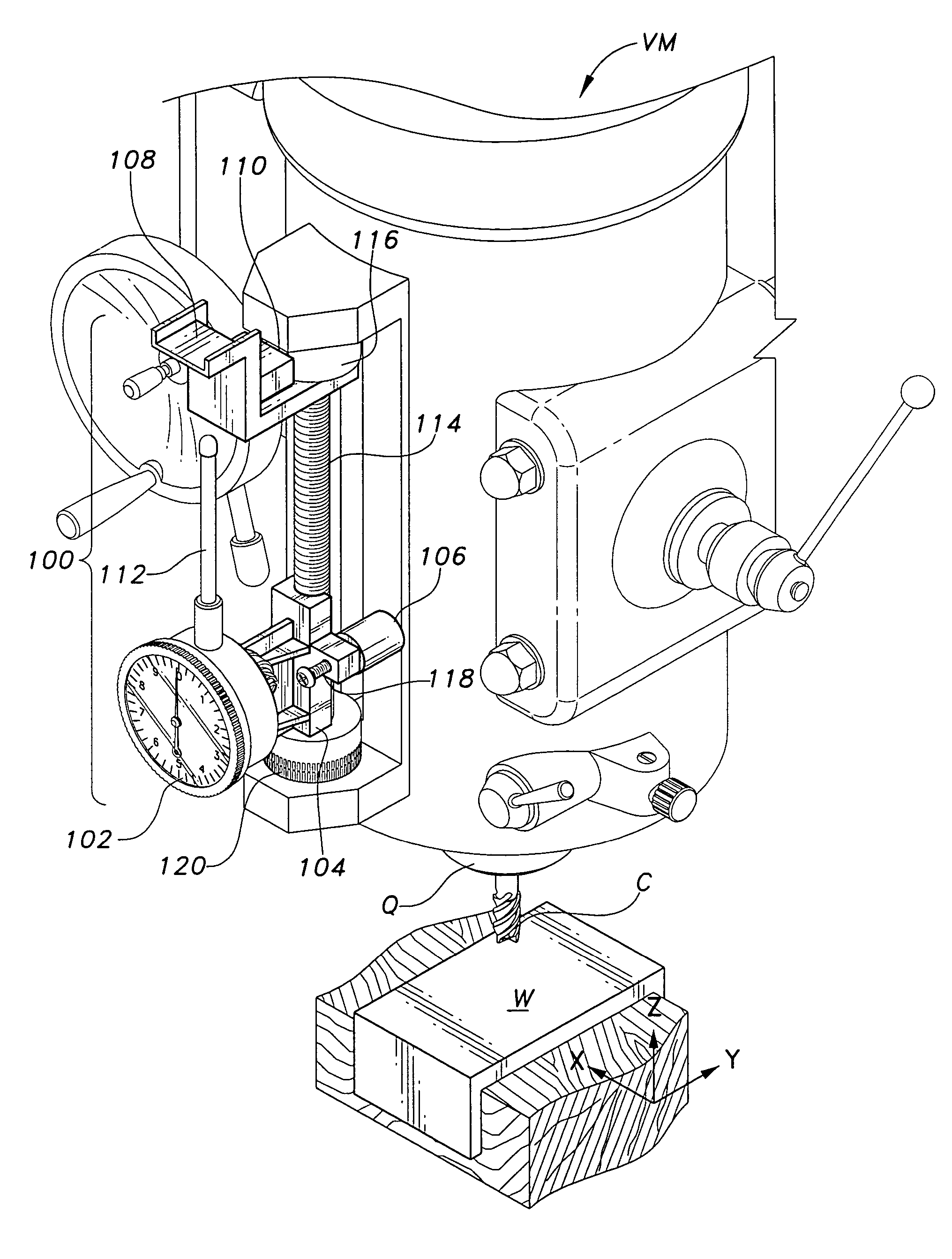
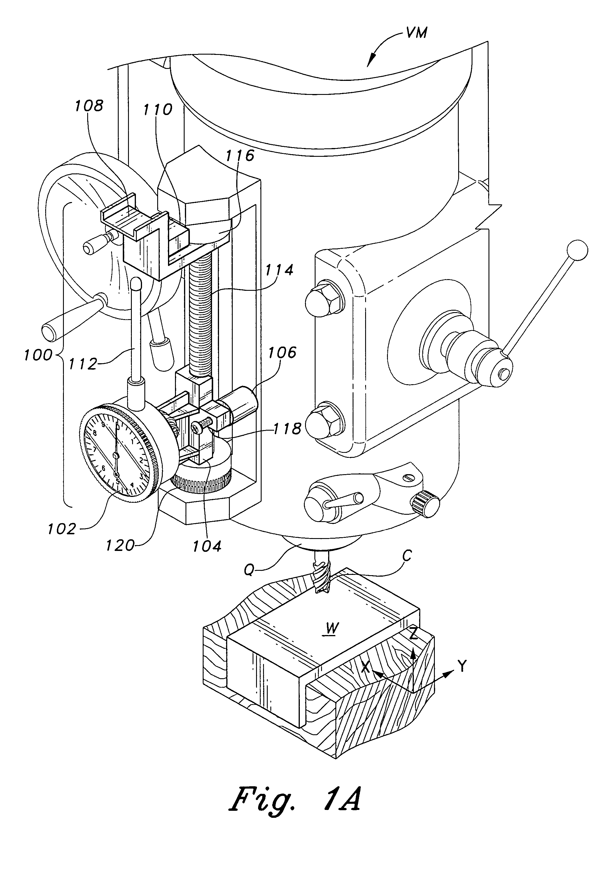
[0035] The present invention, designated generally as 100 in the drawings, is a measurement tool having a mounted depth gage 102 of the dial indicator type for precisely measuring the quill travel, and hence the depth of the cutter C along the Z-axis of a vertical milling machine VM.

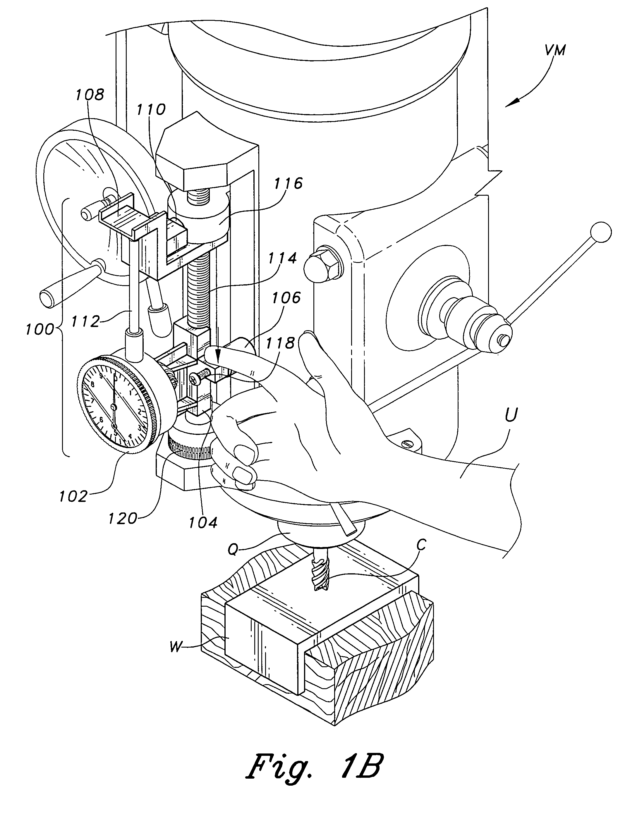
[0036] Referring first to FIG. 6, many commercially available vertical milling machines VM, such as those made by Bridgeport Machines, Inc., have, as standard equipment, a mechanism for limiting the vertical displacement or travel of the quill Q as the attached cutter C penetrates into the surface of the workpiece W. This mechanism consists of a quill stop 116, which travels along a vertically oriented quill stop micro screw 114 until a micrometer adjusting nut 120 stops the downward travel of the quill stop 116.

[0037] During automatic quill feed, the pressure generated kicks the feed control lever out, thereby stopping automatic quill feed. Automatic quill feed is not often used when close tolerance i...


PUM

PropertyMeasurementUnit
Magnetismaaaaaaaaaa
Displacementaaaaaaaaaa

Abstract

The “Z”-axis measurement tool is an adapter having a mounted depth gage for precise measurement of the vertical displacement of the cutting edge of a vertical milling machine. The tool has a first magnetically mountable bracket slidably attached to a stationary portion of a vertical milling machine, and a second bracket removably mounted to the quill stop of the milling machine. A depth gage mounted to the first bracket has an upward extending spindle which cooperatively engages a flat surface on the second bracket when the quill stop descends as the quill is lowered to engage a workpiece with a cutter.

Description

BACKGROUND OF THE INVENTION [0001] 1. Field of the Invention [0002] The present invention relates generally to attachments for machine tools. More particularly, the Z-axis measurement tool relates to a holder assembly for an indicator for use with vertical milling machines to measure the vertical travel, or milling depth, of a quill mechanism. [0003] 2. Description of the Related Art [0004] Milling machines are used for removing metal from a workpiece, and a number of different types of milling machines are commercially available. These commercially available milling machines often are classified as either vertical or horizontal. In the horizontal milling machines, the rotating spindle is oriented horizontally. In a vertical milling machine, the rotating spindle is vertically disposed, typically for face milling and end milling. [0005] The vertical milling machine is a versatile shop tool. For example, in a knee and column machine, a worktable is movably mounted on a saddle, which i...

Claims


Application Information

Patent Timeline
IPC IPC(8): B23C1/12B23Q17/22
CPCY10T409/308624B23Q17/22
Inventor TIESZEN, DWAYNE A.
Owner TIESZEN DWAYNE A
Why Eureka
Try Eureka