

Light polarization beam splitter
A technology of beam splitter and light polarization, which is applied in the coupling direction of optical waveguide, can solve the problems of not very high extinction ratio, not very large bandwidth, additional loss, etc., and achieve the effect of large bandwidth, high extinction ratio and compact size
- Summary
- Abstract
- Description
- Claims
- Application Information
AI Technical Summary
Problems solved by technology
Method used
Image

Examples
Embodiment Construction
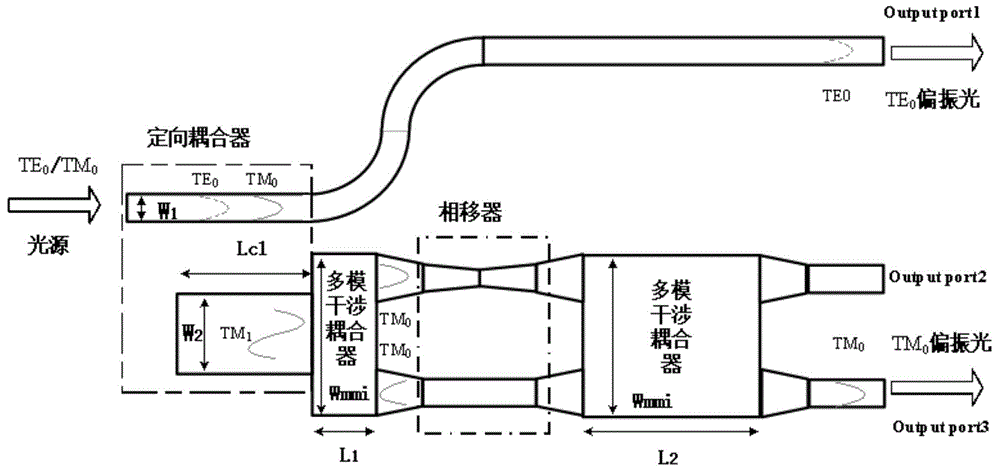
[0026] 1. polarizer structure of the present invention sees attached figure 1 , TE 0 、TM 0 Polarized light passes through the Input port at the same time, that is, the width is W 1 The waveguide port input into this device, propagate independently in the waveguide, TE 0 、TM 0 The light fields are represented by dashed and solid lines, respectively.
[0027] 2. For TM 0 Input light, based on the principle of coupled mode theory and phase matching, design a suitable waveguide width, so that the width is W 1 TM in the waveguide 0 The propagation constant of light is equal to the width W 2 (W 1 2 ) in the waveguide TM 1 The propagation constant (β TM0 = β TM1 ), satisfying the principle of phase matching, TM 0 Light can be coupled from a narrow waveguide to a wide waveguide, and by TM 0 mode into TM 1 Mode propagation, and the length of the wide waveguide satisfies the coupling length Lc1, so that the energy of the input light is maximized from W 1 waveguide coupled...
PUM
 Abstract
Description
Claims
Application Information