Waste compaction and lift gate mechanism

a technology of waste and gate mechanism, which is applied in the direction of presses, press rams, manufacturing tools, etc., can solve the problems of unsanitary hinged gate, potential injuries, and bins often filled

Inactive Publication Date: 2013-04-16
KACHKOVSKY OLIVER
View PDF12 Cites 5 Cited by
  • Summary
  • Abstract
  • Description
  • Claims
  • Application Information

AI Technical Summary

Problems solved by technology

However, the waste bins are often filled with trashes that have high air content such as cup, boxes, and other containers that retain their structure.
With frequent disposal of waste, the hinged gate slowly becomes unsanitary.
Furthermore, the possibility of having ones fingers caught between the gate and the waste bin wall is present and may cause potential injuries.

Method used


Image

  • Waste compaction and lift gate mechanism
  • Waste compaction and lift gate mechanism
  • Waste compaction and lift gate mechanism

Examples


Embodiment Construction

[0029]All illustrations of the drawings are for the purpose of describing selected versions of the present invention and are not intended to limit the scope of the present invention. The present invention is a waste compacting device with automated gate lifting abilities.

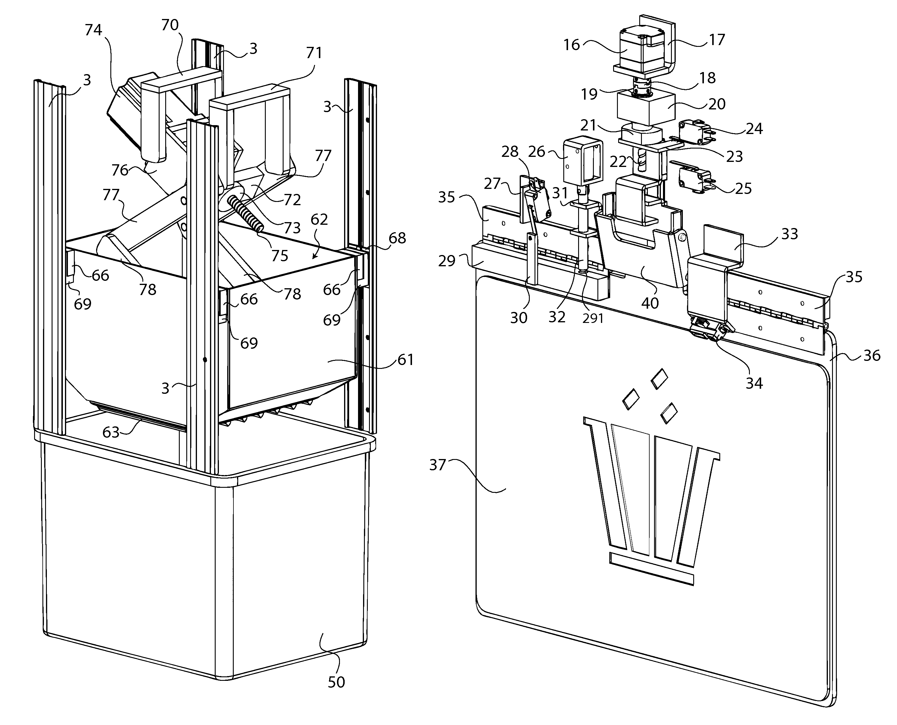
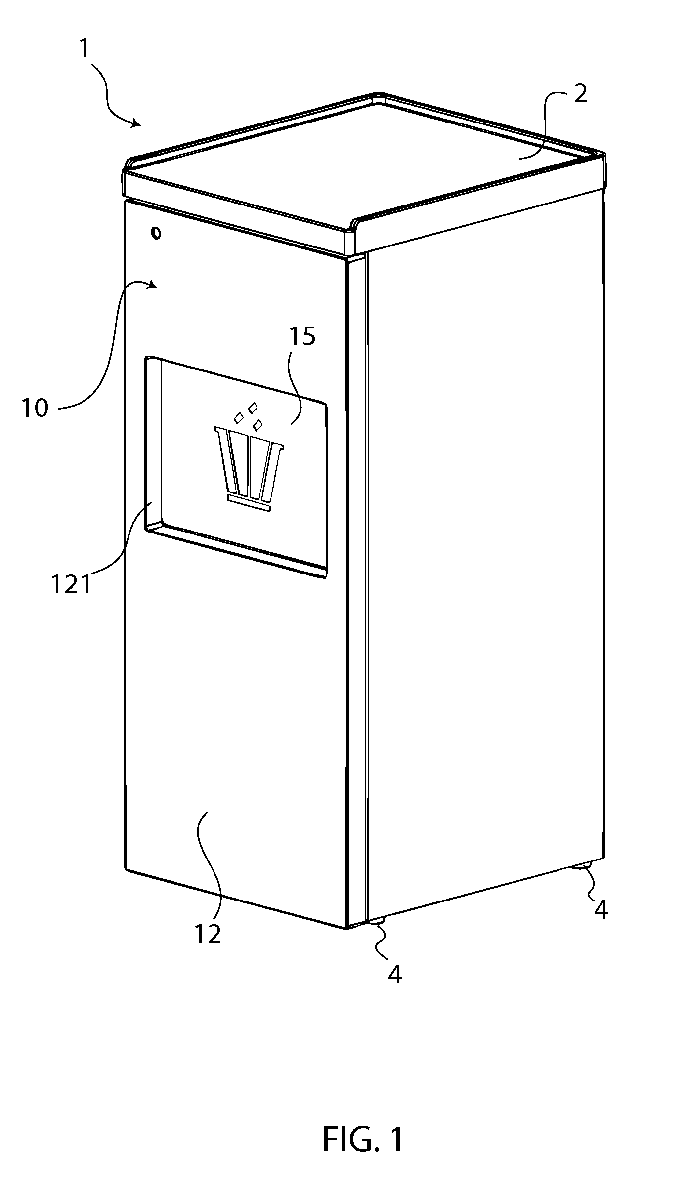
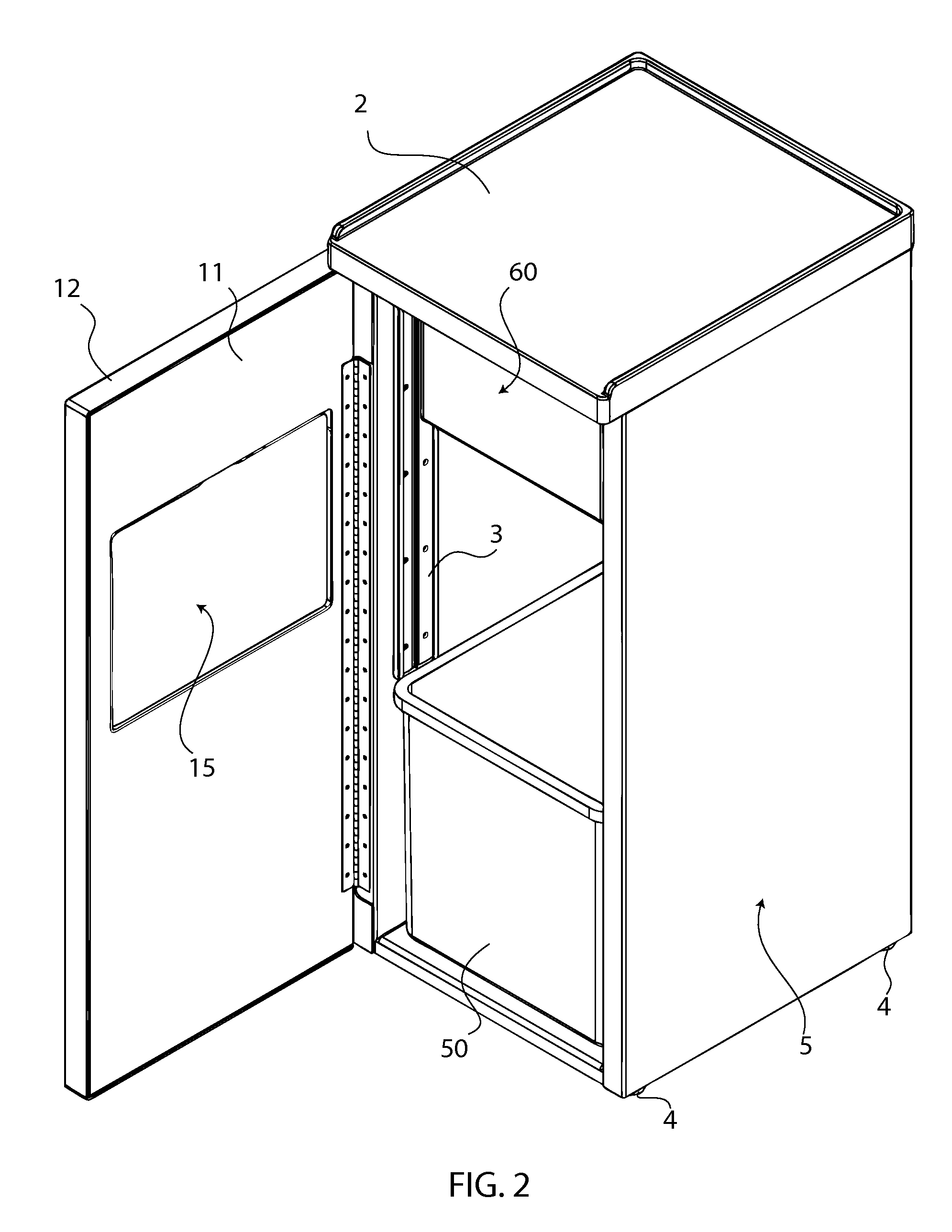
[0030]In reference to FIG. 1, FIG. 2 and FIG. 4, the present invention comprises an external body 1, a waste receptacle 50, and a compacting mechanism 60. The external body 1 of the present invention defines the waste bin for the collection of the waste. The external body 1 is the main body of the present invention and acts as a frame to hold all of the components. The waste receptacle 50 is a removable container that is position in the external body 1 that waste is stored in for compaction and disposal. The compacting mechanism 60 is positioned within the external body 1 above the trash receptacle.

[0031]In reference to FIG. 1-3, the external body 1 comprises a tray holder 2, linear guide rails 3, leveling feet 4, a...


PUM


Abstract

A waste bin with an automated waste compaction mechanism and a automated gate lifting mechanism for convenience usage. The present invention makes use of sensors and switches to allow the compaction and gate mechanism to operate automatically. The unique combination of components also ensures the reliability of the mechanism.

Description

[0001]The current application claims a priority to the U.S. Provisional Patent application Ser. No. 61 / 276,252 filed on Sep. 10, 2009.FIELD OF THE INVENTION[0002]The present invention relates generally to a device used to collect trash. More specifically, the trash collecting device further comprises of an automated compaction device and an automated gate lifting mechanism.BACKGROUND OF THE INVENTION[0003]Typically, the amount, the density, and the other characteristics of waste vary across different industries. Wastes that possess the highest air content can easily benefit the use of trash compaction. In settings such as fast food restaurants, traditional waste bins are easily filled and require the emptying and replacement of the waste receptacle. However, the waste bins are often filled with trashes that have high air content such as cup, boxes, and other containers that retain their structure. With a trash compacting device, fewer trips to the waste bins are necessary to empty t...

Claims


Application Information

Patent Timeline
Patent Type & Authority Patents(United States)
IPC IPC(8): B30B15/14B30B15/30B30B1/10
CPCB30B1/103B30B9/3021B30B9/3032B30B15/041B30B9/3007
Inventor KACHKOVSKY, OLIVER
Owner KACHKOVSKY OLIVER
Why Eureka
Try Eureka