
Solid waste pre-compaction device

A waste, pre-compacting technology, applied in the direction of presses, manufacturing tools, etc., can solve the problems of low compaction efficiency of waste compaction devices

Inactive Publication Date: 2021-01-29
叶其胜
View PDF0 Cites 0 Cited by
  • Summary
  • Abstract
  • Description
  • Claims
  • Application Information

AI Technical Summary

Problems solved by technology

[0004] In order to make up for the above deficiencies, the present invention provides a solid waste pre-compaction device, which aims to improve the problem of relatively low compaction efficiency of the waste product compaction device

Method used


Image

  • Solid waste pre-compaction device
  • Solid waste pre-compaction device
  • Solid waste pre-compaction device

Examples


Embodiment 1

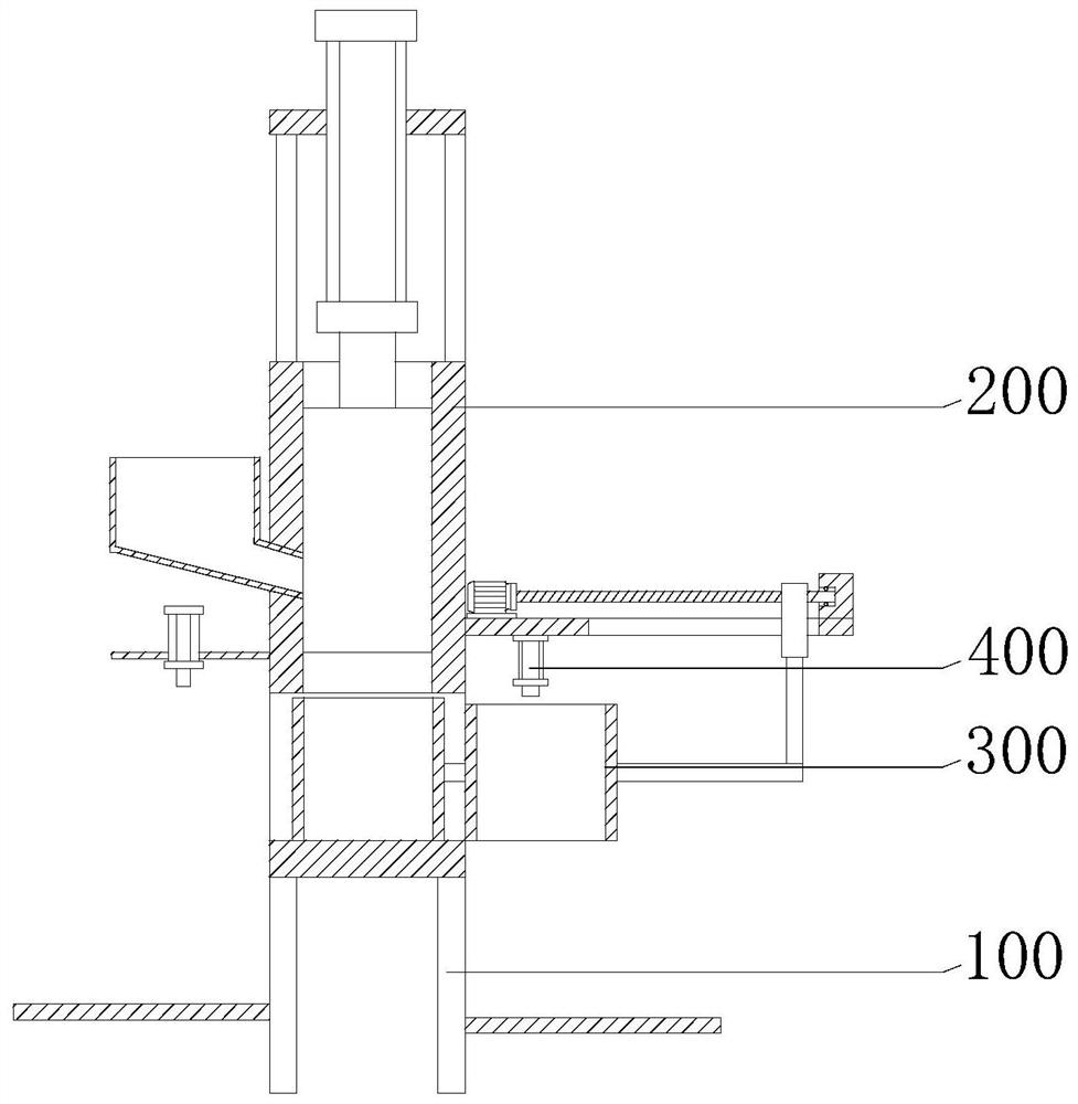
[0027] see figure 1 , the present invention provides a solid waste pre-compacting device including a support base 100 , a compaction assembly 200 and a storage and discharge assembly 300 .

[0028] The compaction assembly 200 and the storage and discharge assembly 300 are both connected to the support base 100, the support base 100 is used for support, the compaction assembly 200 is used for compaction, and the storage and discharge assembly 300 is used for material storage and automatic discharge .

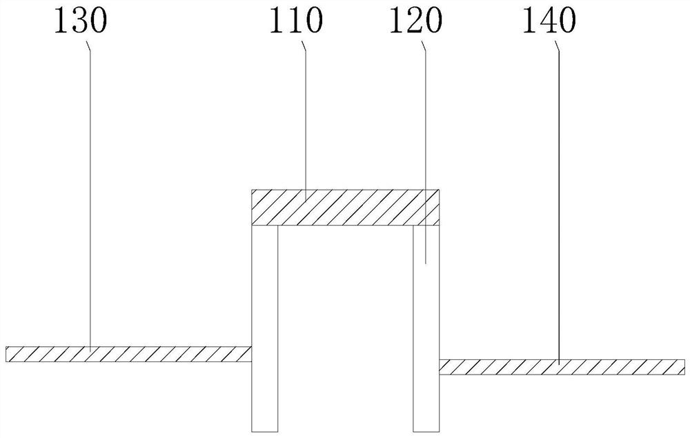
[0029] see figure 2 , the support base 100 includes a support plate 110, a support leg 120, a plurality of support legs 120 are provided, the plurality of support legs 120 are connected to the lower surface of the support plate 110, and the plurality of support legs 120 are connected to the support plate 110 by welding. On the lower surface, the support legs 120 support the support plate 110 for ease of use.

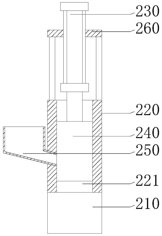
[0030] see image 3, the compaction assembly 200 includes a first...

Embodiment 2

[0038] see figure 1 , the present invention provides a solid waste pre-compacting device including a support base 100 , a compaction assembly 200 and a storage and discharge assembly 300 .

[0039] The compaction assembly 200 and the storage and discharge assembly 300 are both connected to the support base 100, the support base 100 is used for support, the compaction assembly 200 is used for compaction, and the storage and discharge assembly 300 is used for material storage and automatic discharge .

[0040] see figure 2 , the support base 100 includes a support plate 110, a support leg 120, a plurality of support legs 120 are provided, the plurality of support legs 120 are connected to the lower surface of the support plate 110, and the plurality of support legs 120 are connected to the support plate 110 by welding. On the lower surface, the support legs 120 support the support plate 110 for ease of use.

[0041] see image 3 , the compaction assembly 200 includes a firs...


PUM


Abstract

The invention provides a solid waste pre-compaction device, and belongs to the technical field of waste recovery. The waste compaction device comprises a supporting base, a compacting assembly and a material storing and discharging assembly. The compacting assembly comprises a first fixing plate, a connecting sleeve, a first air cylinder, a compression block and a feeding funnel, and the materialstoring and discharging assembly comprises a first material storing barrel, a second material storing barrel, an electric guide rail and a first connecting rod. During usage, the first air cylinder drives the compression block to move upwards, so that the compression block does not block the discharging end of the feeding funnel any more, then waste in the feeding funnel can fall into the first material storing barrel through a first sliding groove, then the first air cylinder drives the compression block to move downwards to compress the waste in the first material storing barrel, at the moment, the compacted waste in the second material storing barrel can be automatically discharged under the action of gravity, then, manual unloading is not needed, a large amount of manpower can be saved, and therefore the compaction efficiency of the waste compaction device can be improved.

Description

technical field [0001] The invention relates to the field of waste recycling, in particular to a solid waste pre-compacting device. Background technique [0002] Waste recycling is a common measure to protect the environment, especially industrial waste, which needs to be collected in a centralized manner for pollution-free treatment. Industrial wastes such as small paint buckets, small waste oil buckets, waste rags, plastic bottles and cans take up a lot of space during transportation, so they need to be compressed and compacted. [0003] However, most of the existing waste compaction devices mostly require manual and frequent unloading, and a large number of waste products are compacted together after being compressed, so that the compacted waste products have a certain weight, thus making manual loading down The material will be very laborious, thereby making the compaction efficiency of the waste compaction device relatively low. SUMMARY OF THE INVENTION [0004] In ...

Claims


Application Information

Patent Timeline
Patent Type & Authority Applications(China)
IPC IPC(8): B30B9/30
CPCB30B9/3003B30B9/301B30B9/3014B30B9/305B30B9/3057
Inventor 叶其胜
Owner 叶其胜
Learn More