
Tamping device for road engineering

A tamping device and road engineering technology, which is applied in the direction of roads, roads, road repairs, etc., can solve the problems of high transportation and use costs, unsuitable roads, and low operating efficiency, so as to improve tamping efficiency, avoid manual cleaning, and simple structure Effect

Inactive Publication Date: 2018-09-28
FOSHAN XINLAI ENG TECH CO LTD
View PDF8 Cites 4 Cited by
  • Summary
  • Abstract
  • Description
  • Claims
  • Application Information

AI Technical Summary

Problems solved by technology

[0002] A compactor is a building construction machine used to tamp the ground. In road engineering operations, a compactor is needed to compact the roadbed composed of soil and gravel, which is convenient for laying cement or asphalt. Traditional hand-held compactors are used for compaction. The area of ​​the surface is small and the work efficiency is low. It is obviously not suitable for road construction. Using large-scale compaction equipment, although the compaction effect is good, but the transportation and use costs are high, and a large work space is required, so it is not suitable for some small-scale road operations. , not economical and inconvenient. In addition, when the tamping block of the traditional tamping equipment is being tamped, the edge of the tamping block is easy to squeeze out the soil and stones to the outside, and manual backfilling is required, which reduces the construction efficiency and ensures the quality of the tamping. In addition, it is easy to cause stones to splash, threaten the safety of workers, and even cause safety accidents

Method used


Image

  • Tamping device for road engineering
  • Tamping device for road engineering
  • Tamping device for road engineering

Examples


Embodiment Construction

[0019] The following will clearly and completely describe the technical solutions in the embodiments of the present invention with reference to the accompanying drawings in the embodiments of the present invention. Obviously, the described embodiments are only some, not all, embodiments of the present invention. Based on the embodiments of the present invention, all other embodiments obtained by persons of ordinary skill in the art without making creative efforts belong to the protection scope of the present invention.

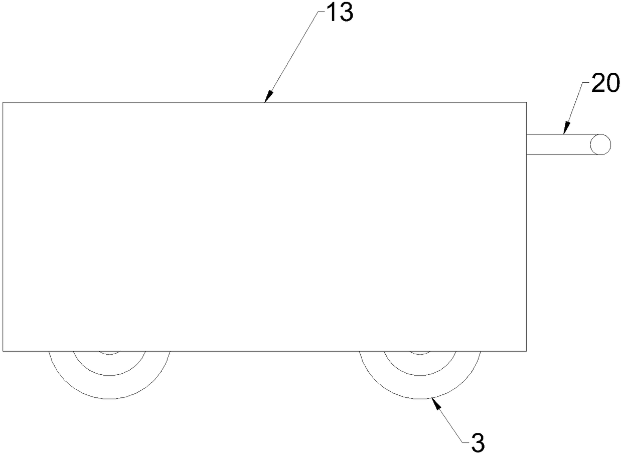
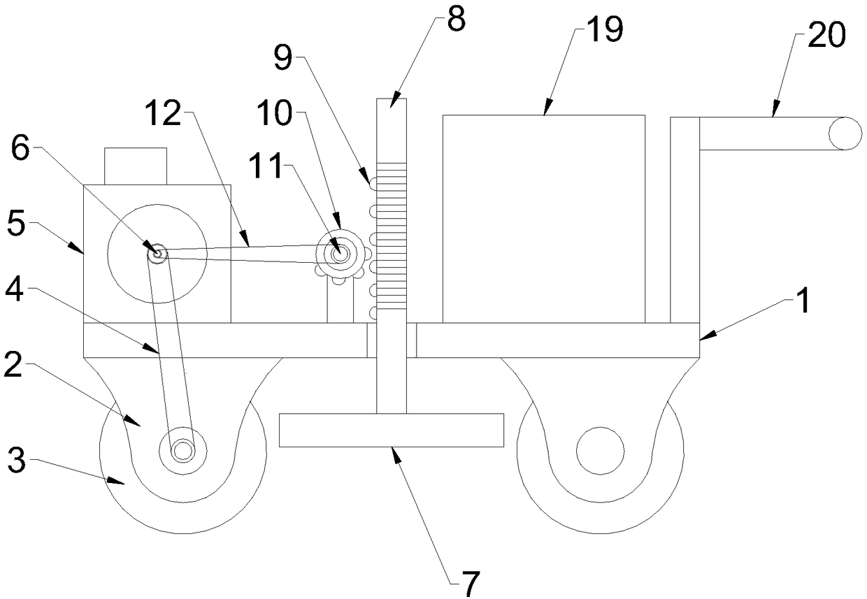
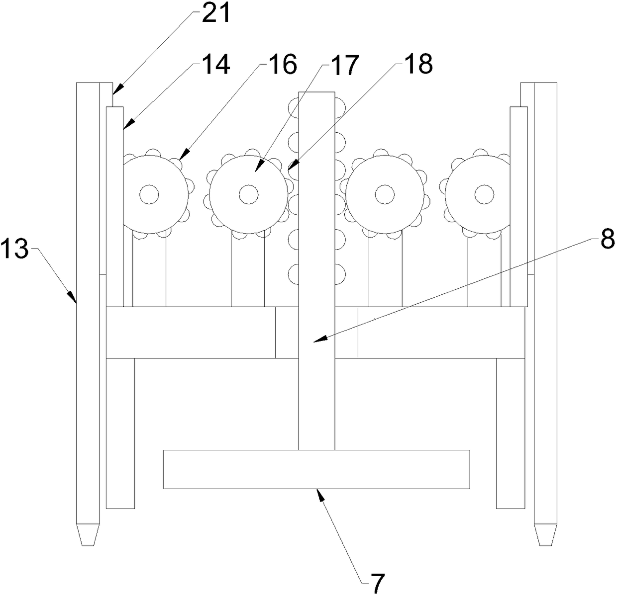
[0020] see Figure 1~5 , in the embodiment of the present invention, a kind of tamping device for road engineering, comprises car board 1, compacting roller 3 and diesel engine 5; Said car board 1 is provided with left-right symmetrical compacting roller 3, and compacting roller 3 is rotationally connected There is a side plate 2, and the side plate 2 is fixedly connected to the bottom of the vehicle plate 1; the compacting roller 3 is connected to the output ...


PUM


Abstract

The invention discloses a tamping device for road engineering. The tamping device for road engineering comprises a vehicle board, compaction rollers and a diesel engine; the bilaterally symmetrical compaction rollers are arranged under the vehicle board; an output shaft of the diesel engine is connected to the compaction roller through a first transmission belt; and a compaction block is arrangedbetween the compaction rollers. According to the tamping device for road engineering, through adoption of the compaction rollers and the diesel engine, the diesel engine drives the compaction rollersto rotate to compact soils in a mobile manner; by arranging the compaction block and using a limiting plate which is linked with a mobile rod through a transmission mechanism, materials which extrudedoutwards during tamping the compaction block are limited to improve the tamping effect, avoid manual cleaning and enhance the tamping efficiency; and the tamping device for road engineering has the advantages that the structure is simple, the volume is small, the tamping device can adapt to multiple operation scenes, and the practicability is high.

Description

technical field [0001] The invention relates to the field of road engineering, in particular to a compacting device for road engineering. Background technique [0002] A compactor is a building construction machine used to tamp the ground. In road engineering operations, a compactor is needed to compact the roadbed composed of soil and gravel, which is convenient for laying cement or asphalt. Traditional hand-held compactors are used for compaction. The area of ​​the surface is small and the work efficiency is low. It is obviously not suitable for road construction. Using large-scale compaction equipment, although the compaction effect is good, but the transportation and use costs are high, and a large work space is required, so it is not suitable for some small-scale road operations. , not economical and inconvenient. In addition, when the tamping block of the traditional tamping equipment is being tamped, the edge of the tamping block is easy to squeeze out the soil and st...

Claims


Application Information

Patent Timeline
IPC IPC(8): E01C19/22
CPCE01C19/22
Inventor 王利
Owner FOSHAN XINLAI ENG TECH CO LTD
Learn More