Quick pressing mechanism for mechanical manufacturing equipment

A compression mechanism and mechanical manufacturing technology, applied in the direction of manufacturing tools, metal processing equipment, metal processing machinery parts, etc., can solve the problems of manual adjustment of the compression height, inability to adjust the compression angle, time-consuming and labor-intensive problems, etc., to achieve Pressing angle adjustment, fast pressing, easy to use

Active Publication Date: 2020-05-19
CHANGZHOU INST OF MECHATRONIC TECH +1
View PDF5 Cites 4 Cited by
  • Summary
  • Abstract
  • Description
  • Claims
  • Application Information

AI Technical Summary

Problems solved by technology

[0003] 1. The pressing height needs to be adjusted manually. When pressing at multiple pressing points, the debugging process is more cumbersome, so it is time-consuming and labor-intensive;
[0004] 2. Its compression length cannot be effectively adjusted automatically, so the compression range in its application is limited to a certain extent;
[0005] 3. The pressing angle cannot be adjusted. When pressing on an inclined surface, the pressing angle cannot be directly adjusted. If necessary, a specific angle support tool needs to be added, which is extremely inconvenient to use

Method used


Image

  • Quick pressing mechanism for mechanical manufacturing equipment
  • Quick pressing mechanism for mechanical manufacturing equipment
  • Quick pressing mechanism for mechanical manufacturing equipment

Examples


Embodiment Construction

[0033] The following will clearly and completely describe the technical solutions in the embodiments of the present invention with reference to the accompanying drawings in the embodiments of the present invention. Obviously, the described embodiments are only some, not all, embodiments of the present invention. Based on the embodiments of the present invention, all other embodiments obtained by persons of ordinary skill in the art without making creative efforts belong to the protection scope of the present invention.

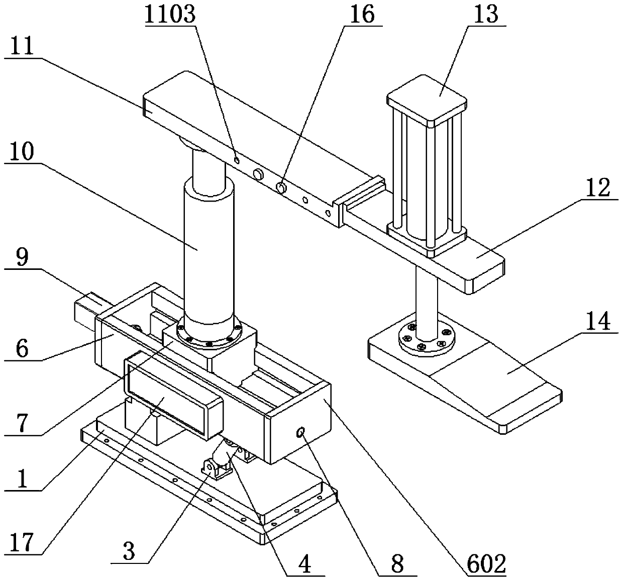
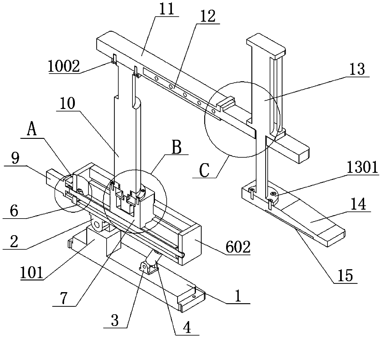
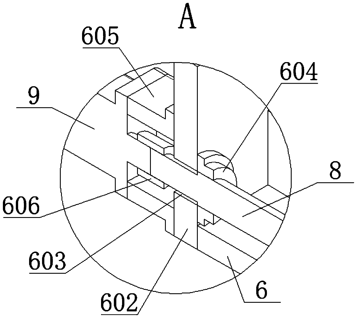
[0034] see Figure 1-7 , the present invention provides a technical solution:

[0035] A quick pressing mechanism for mechanical manufacturing equipment, comprising an overturning component, a sliding component set on the upper end of the overturning component, and a pressing component set on the upper end of the sliding component, a support base 1 is provided at the lower end of the overturning component, and The left side of the hinged seat I101 is provided...


PUM


Abstract

The invention relates to the technical field of machining, and particularly discloses a quick pressing mechanism for mechanical manufacturing equipment. The quick pressing mechanism for the mechanicalmanufacturing equipment comprises a turnover assembly, a sliding assembly arranged at the upper end of the turnover assembly and a downward pressing assembly arranged at the upper end of the slidingassembly, wherein the sliding assembly is composed of a fixed seat of a groove body structure, a sliding seat, a worm and a driving motor; and the downward pressing assembly consists of a lifting electric cylinder, a fixed plate, an extension plate, a downward pressing electric cylinder and a pressing plate. According to the quick pressing mechanism for the mechanical manufacturing equipment, thetelescopic length of the downward pressing electric cylinder can be directly set through a touch display screen, so that the pressing height of the pressing plate at the lower end of the downward pressing electric cylinder is controlled; the worm is driven by the driving motor to be engaged with a transmission turbine tooth head for transmission, so that the sliding seat moves left and right in the fixed seat along the guide of a guide groove, and the pressing length of the pressing plate relative to a workpiece can be quickly adjusted; and the pressing angle of the whole mechanism can also beeffectively adjusted, and rapid pressing can be realized by using the quick pressing mechanism.

Description

technical field [0001] The invention relates to the technical field of mechanical processing, in particular to a quick pressing mechanism for mechanical manufacturing equipment. Background technique [0002] In the machining process, the positioning and installation of the workpiece is one of the important links. The accuracy of the positioning and installation of the workpiece determines the basic accuracy of the machining to a certain extent, and the positioning and installation of the workpiece on the machine tool is usually completed by positioning tooling and pressing tooling. Positioning installation, where the compression tooling is usually divided into ordinary compression tooling and quick compression tooling, and the main representative of the quick compression tooling is the quick clamp. In actual production, the corresponding quick clamp tooling is selected according to different workpieces. The structure is relatively simple, but it still has the following short...

Claims


Application Information

Patent Timeline
Patent Type & Authority Applications(China)
IPC IPC(8): B23Q3/06
CPCB23Q3/06
Inventor 于华艳朱文杰蔡福海庄百亮虞文武张江华
Owner CHANGZHOU INST OF MECHATRONIC TECH
Why Eureka
Try Eureka