
Tubes and their manufacture

a technology of tubes and end fittings, applied in the field of tubes, can solve the problems of difficult to securely attach a hub or end fitting to the machine end of the shaft of the cannula in a reliable and low cost manner, and achieve the effect of improving the safety of use and reducing the risk of injury

Active Publication Date: 2013-04-16
SMITHS MEDICAL INT
View PDF20 Cites 8 Cited by
  • Summary
  • Abstract
  • Description
  • Claims
  • Application Information

AI Technical Summary

Benefits of technology

The patent is looking to provide an alternative tube and a method for manufacturing it. The technical effect of this invention is to offer a new option for tubes that can be used in various applications.

Problems solved by technology

The inner tube presents various problems because it must be thin walled and a close fit within the outer tube so as to limit the resistance to flow of gas along the assembly.
Whilst such a material has various advantages, the material makes it difficult to attach a hub or end fitting to the machine end of the shaft of the cannula securely in a reliable and low cost manner.
There are also other tubes where it can be difficult to attach an end fitting.

Method used


Image

  • Tubes and their manufacture
  • Tubes and their manufacture
  • Tubes and their manufacture

Examples


Embodiment Construction

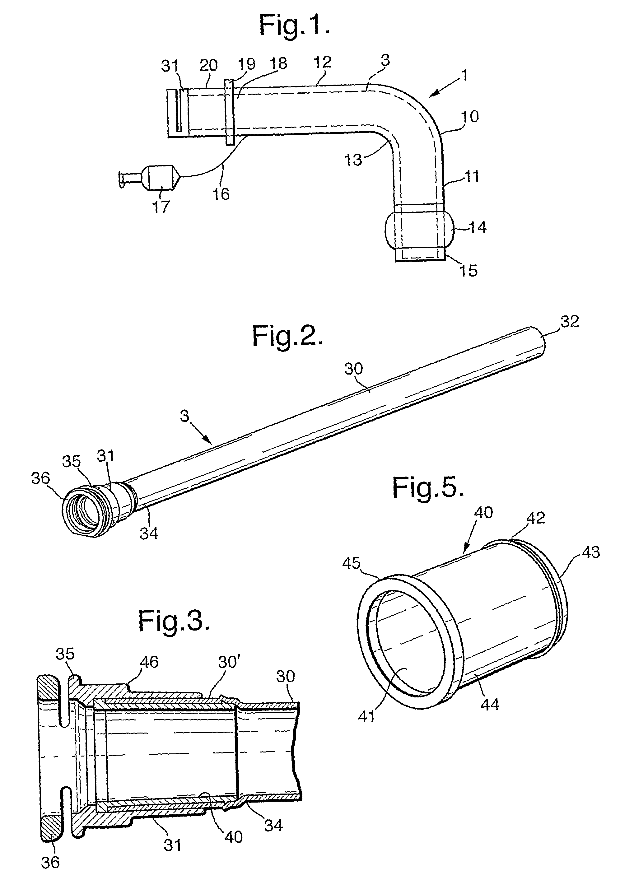
[0018]With reference first to FIG. 1, the tracheostomy tube assembly comprises an outer tube 1 and an inner tube or cannula 3, which is removable from the outer tube so that it can be periodically replaced in the usual way.

[0019]The outer tube 1 is entirely conventional having a shaft 10 with straight forward or patient end section 11 and rear or machine end section 12 joined by a right-angle bend section 13. Alternative outer tubes could be smoothly curved along their entire length or could be highly flexible and reinforced with a natural straight shape. A sealing cuff 14 embraces the shaft 10 close to its patient end 15; this can be inflated for sealing, or deflated for insertion and removal, via an inflation line 16 and a combined inflation indicator balloon and coupling 17. At its rear end 18, the outer tube 1 has a flange 19 to which a tape (not shown) can be attached for securing the assembly around the neck of the patient. A hub 20 projects from the machine side of the flange...


PUM

PropertyMeasurementUnit
external diameteraaaaaaaaaa

Abstract

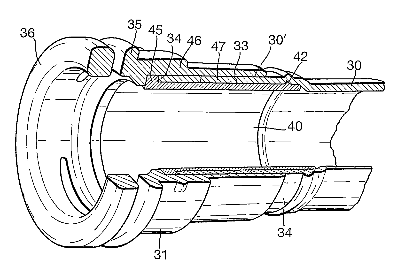
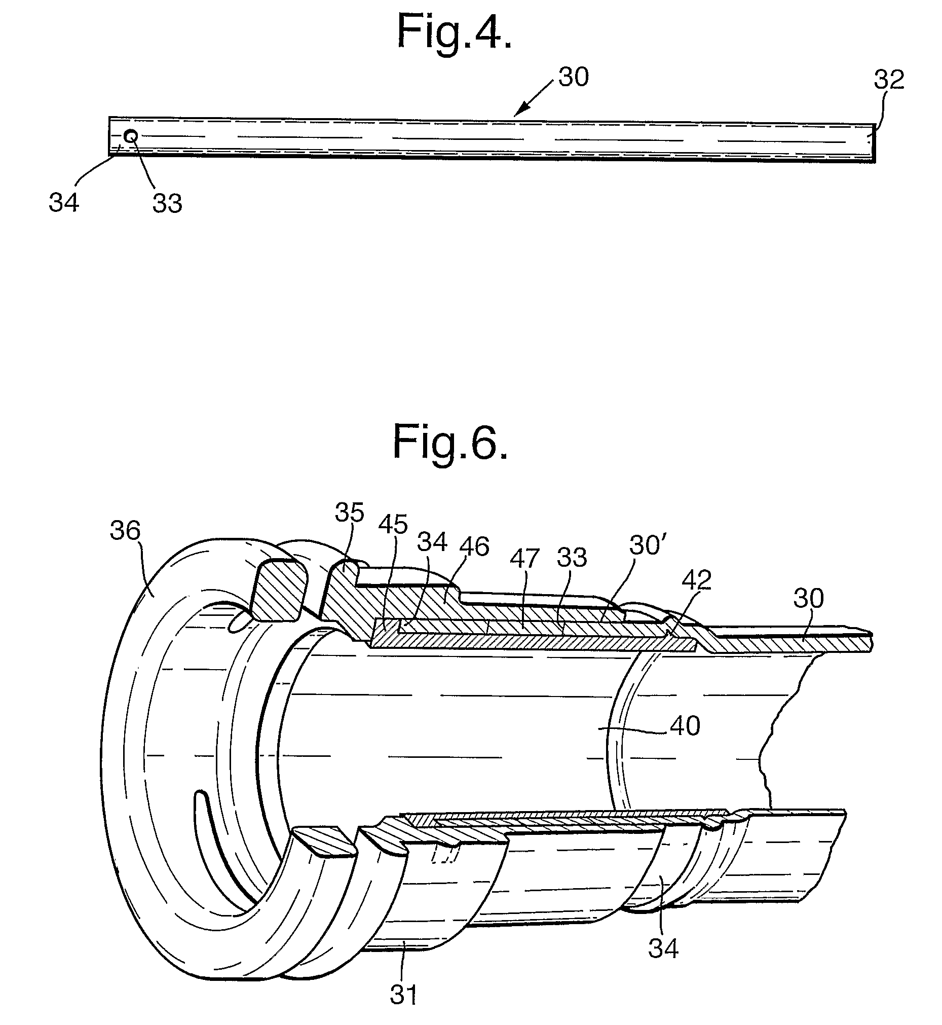
An end fitting (31) is formed at the patient end of an inner cannula (3) for a tracheostomy tube (1) by punching small holes (33) close to one end (34) of an ePTFE shaft (30). The end is then swaged to form an expanded region (30′) and a preformed tubular insert (40) of a thermoplastic material is inserted to cover the holes (33) on the inside. An outer part (46) of the same thermoplastic material is then overmolded on the outside of the shaft 30 so that its material (47) flows through the holes (33) and bonds with the inner insert (40), thereby securing the inner and outer parts together around the end of the shaft.

Description

FIELD OF INVENTION[0001]This invention relates to tubes of the kind having a shaft and an end fitting attached with the shaft at one end.BACKGROUND OF INVENTION[0002]Tubes are used in many medical and non-medical applications. For example, tracheostomy tube assemblies commonly include an outer tube and an inner tube or cannula that is a removable fit within the outer tube. The inner tube can be removed and replaced periodically to ensure that the passage through the assembly does not become blocked by secretions. This avoids the need frequently to remove the outer tube.[0003]The inner tube presents various problems because it must be thin walled and a close fit within the outer tube so as to limit the resistance to flow of gas along the assembly. It must, however, also be sufficiently stiff to be inserted in the outer tube without buckling or kinking. A particularly suitable material for the inner cannula is PTFE or expanded PTFE (ePTFE). The use of such a material in an inner cannu...

Claims


Application Information

Patent Timeline
Patent Type & Authority Patents(United States)
IPC IPC(8): F16L47/00
CPCA61M16/0427A61M16/0465
Inventor NEAME, SIMON
Owner SMITHS MEDICAL INT
Learn More