Spring loaded pressure relief door

a technology of springs and relief doors, applied in the direction of simulator control, aircraft power transmission, lighter-than-air aircraft, etc., can solve the problems of sudden thrust loss, engine over-temperature, and major contributory noise of aircraft engines, and achieve the effect of increasing the durability of the spring elemen

Active Publication Date: 2013-05-14
THE BOEING CO
View PDF10 Cites 14 Cited by
  • Summary
  • Abstract
  • Description
  • Claims
  • Application Information

AI Technical Summary

Benefits of technology

[0014]In still another variation of the disclosure, as the door panel closes, the distance between the axis of compression and the second pivot axis increases so that the compressive force on the spring element is relieved.
[0015]In yet another variation of the disclosure, as the door panel opens, the distance between the axis of compression of the canister and the second pivot axis decreases thereby compressing the spring element in the canister, and as the door panel closes, the distance between the axis of compression and the second pivot axis increases so that the compressive force on the spring element is relieved, whereby a near constant opening and closing force controls the motion of the door panel throughout the entire range of motion of the door panel.
[0016]In yet another variation of the disclosure, the spring element is entirely housed within the canister and the canister shields the spring element from impingement of hot gases from the engine operating inside the engine compartment when the door panel is closed, thereby increasing the durability of the spring element.
[0017]In yet another variation of the disclosure, slots are provided in diametrically opposed sides of the canister in the vicinity of the canister open end, and a spring retainer supports stop pins that fit in and ride along the slots, the slots having a finite axial extent so that when the door panel opens it is prevented from hitting structural parts located outside the engine compartment.
[0021]In still another variation of the disclosure, a method of relieving excessive pressure within an engine compartment by opening and closing a pressure relief door blocking an opening in an engine compartment comprises the steps of mounting the pressure relief door on the wall in blocking relationship to the opening, pivotally securing the door to an inner surface of the engine compartment so that the door opens outwardly of the engine compartment when pressure in the engine compartment exceeds a threshold amount, attaching a spring between the door and the inner surface of the engine compartment so that the spring holds the door in a first position wherein the opening is closed, and compressing the spring by a threshold amount such that the door will move away from the opening only when the pressure in the engine compartment exceeds the threshold force.
[0023]Another variation of the method includes the steps of providing a pivot between the door and the inner surface of the engine compartment, and arranging the spring relative to the pivot such that as the door opens, the distance between the spring axis of compression and the pivot decreases thereby compressing the spring element, and as the door closes, the distance between the spring axis of compression and the pivot increases so that the compressive force on the spring element is relieved, whereby a near constant opening and closing force controls the motion of the door throughout the entire range of motion of the door.

Problems solved by technology

Aircraft engines are a major contributor to overall aircraft noise.
Excursions beyond the surge line cannot be tolerated inasmuch as surge can result in sudden thrust loss and / or engine over-temperature.
Such an event that is not acceptable.
Another proposed solution involves adding a large vent in the cowling, However, doing so would negatively impact engine performance due to aerodynamic drag in the fan stream.
Still another proposed solution involves increasing the pressure needed to pop open the existing trigger latch pressure relief doors, but this would require strengthening the cowling to withstand increased pressure loads, which in turn would increase the cowling weight.

Method used


Image

  • Spring loaded pressure relief door
  • Spring loaded pressure relief door
  • Spring loaded pressure relief door

Examples


Embodiment Construction

[0031]Embodiments of the present disclosure now will be described more fully hereinafter with reference to the accompanying drawings. However, many different embodiments are contemplated and the present disclosure should not be construed as limited to the embodiments set forth herein; rather, these embodiments are provided so that this disclosure will be thorough and complete and better convey the scope of the disclosure to those skilled in the art.

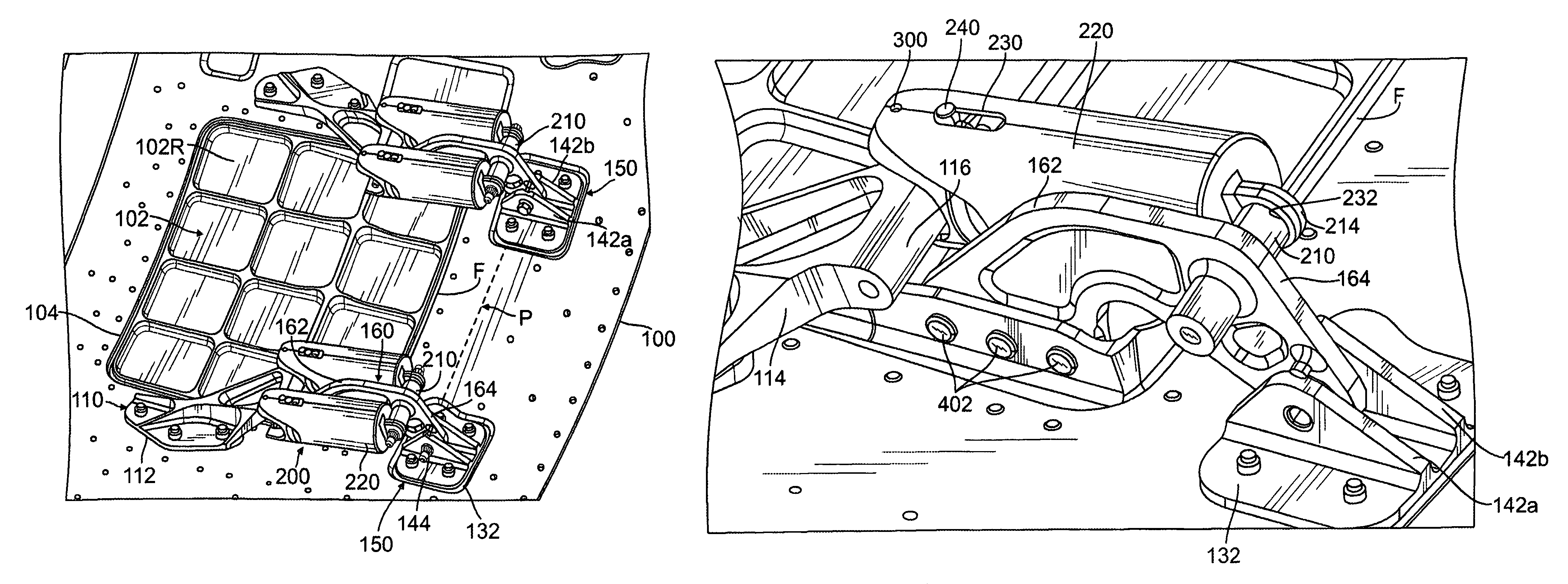
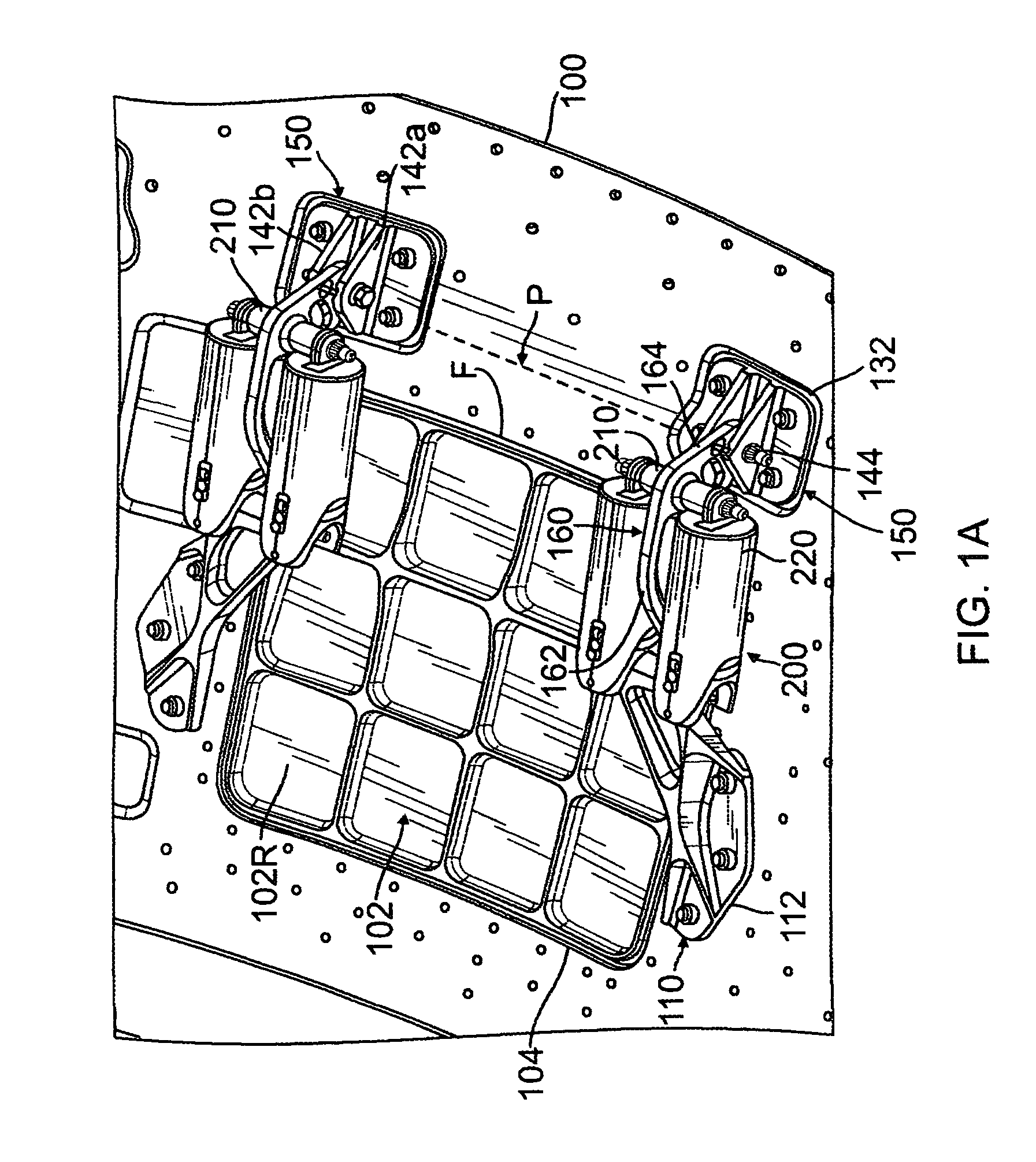
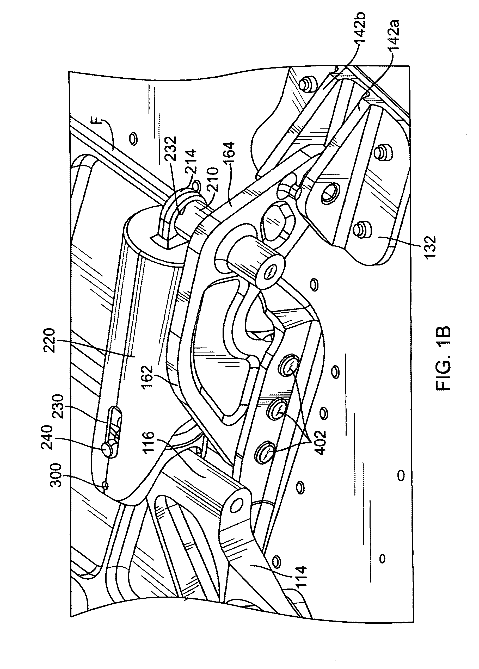
[0032]In its broadest sense, this disclosure presents a pressure relief mechanism including a door for opening an engine compartment subject to a variable pressure environment, where the pressure relief mechanism is actuated when the pressure exceeds a predetermined threshold, and the force for opening or closing the door is substantially constant throughout its entire range of motion.

[0033]The present disclosure further encompasses a structural arrangement for relieving high levels of pressure in a vehicle engine compartment resulting fr...


PUM


Abstract

A pressure relief apparatus for an engine compartment having a wall and an opening in the wall is provided. The pressure relief apparatus includes a door panel arranged in blocking relationship to the opening in the wall of the engine compartment, a plurality of hinges coupling the door panel to an inner surface of the wall of the engine compartment, a spring assembly coupled between each hinge and the inner surface of the wall, wherein the spring assembly includes a canister having an open end and a spring element housed within the canister, and a support fitting mounted to the engine compartment wall and having a portion extending toward the open end of the canister for applying a compressive force on the spring element.

Description

FIELD OF THE DISCLOSURE[0001]The present disclosure relates generally to the field of turbine engines, and more particularly to a nacelle cowl arrangement that permits engine transient bleed air to be released from within an engine housing when pressure exceeds a predetermined threshold.[0002]Aircraft manufacturers are under continual pressure to reduce the noise produced by aircraft in order to satisfy increasingly stringent noise certification rules. Aircraft engines are a major contributor to overall aircraft noise. Aircraft engines have been made significantly quieter as a result of advanced high bypass ratio engines. These engines derive a significant fraction of their total thrust not directly from jet exhaust, but from bypass air which is propelled around the core of the engine by an engine-driven forwardly mounted fan.[0003]It is well-known in the art that it is necessary to operate gas turbine engines close to the engine's surge line in order to transition from one steady-s...

Claims


Application Information

Patent Timeline
Patent Type & Authority Patents(United States)
IPC IPC(8): F16P7/00B64D33/00F24F11/02
CPCB64C7/02B64D29/00G05B21/02G05B17/02G05B13/02F05D2260/38
Inventor ARMSTRONG, MICHAEL E.JONES, MICHAEL D.DUNSTAN, KENT W.
Owner THE BOEING CO
Why Eureka
Try Eureka