
Lighting period setting method, display panel driving method, backlight driving method, lighting condition setting device, semiconductor device, display panel and electronic equipment

a technology of display panel and peak luminance, which is applied in the direction of electric digital data processing, instruments, computing, etc., can solve the problems of display quality degradation of other types of display panels giving priority to motion image response, flicker tends to be conspicuous in this type of panel,

Active Publication Date: 2013-05-14
JOLED INC
View PDF23 Cites 15 Cited by
  • Summary
  • Abstract
  • Description
  • Claims
  • Application Information

AI Technical Summary

Benefits of technology

The patent text discusses the problem of flicker in display panels that prioritize motion image response over quality. Flicker can be visually noticeable in these panels, even at low frames. This issue can result in reduced display quality, and it affects both organic EL and liquid crystal panels. The text describes a method to adjust the frame frequency based on the input image data, providing better determination accuracy for light emission mode. The method also allows for individualized control of lighting periods per field period, providing optimal lighting control for different peak luminance levels. Overall, the patent proposes techniques to improve the quality of display panels, balancing motion image response and flicker reduction.

Problems solved by technology

However, flicker tends to be conspicuous in this type of panel because of its fast motion image response.
It should be noted that this problem also holds true for a liquid crystal panel with improved motion image response.
Thus, the types of display panels giving priority to motion image response are subject to display quality degradation resulting from flicker.
On the other hand, other types of display panels giving priority to countermeasures against flicker are subject to display quality degradation resulting from degradation in motion image response.
Therefore, it is difficult at present to set driving conditions suited to all images.

Method used


Image

  • Lighting period setting method, display panel driving method, backlight driving method, lighting condition setting device, semiconductor device, display panel and electronic equipment
  • Lighting period setting method, display panel driving method, backlight driving method, lighting condition setting device, semiconductor device, display panel and electronic equipment
  • Lighting period setting method, display panel driving method, backlight driving method, lighting condition setting device, semiconductor device, display panel and electronic equipment

Examples


embodiment 1

(B) Embodiment 1

(B-1) System Configuration

[0092]FIG. 4 illustrates a system configuration example of an organic EL panel 11. The organic EL panel 11 includes a pixel array section 13, signal line drive section 15 configured to drive signal lines, control line drive section 17 configured to drive control lines, signal processing section 19 and lighting condition setting section 21. These components are arranged on a glass substrate. In practical circuits, however, only some of the circuits shown in FIG. 4 may be arranged on the same substrate, with the remaining circuits arranged, for example, on a separate substrate.

(a) Pixel Array Section

[0093]The pixel array section 13 has a matrix of subpixels 31 arranged in M rows by N columns. A subpixel is the minimum unit of light emission region. Here, the subpixels 31 are, for example, associated with RGB pixels for the three primary colors making up a white unit.

[0094]FIG. 6 illustrates an example of pixel circuit of the subpixel 31 for ac...


PUM


Abstract

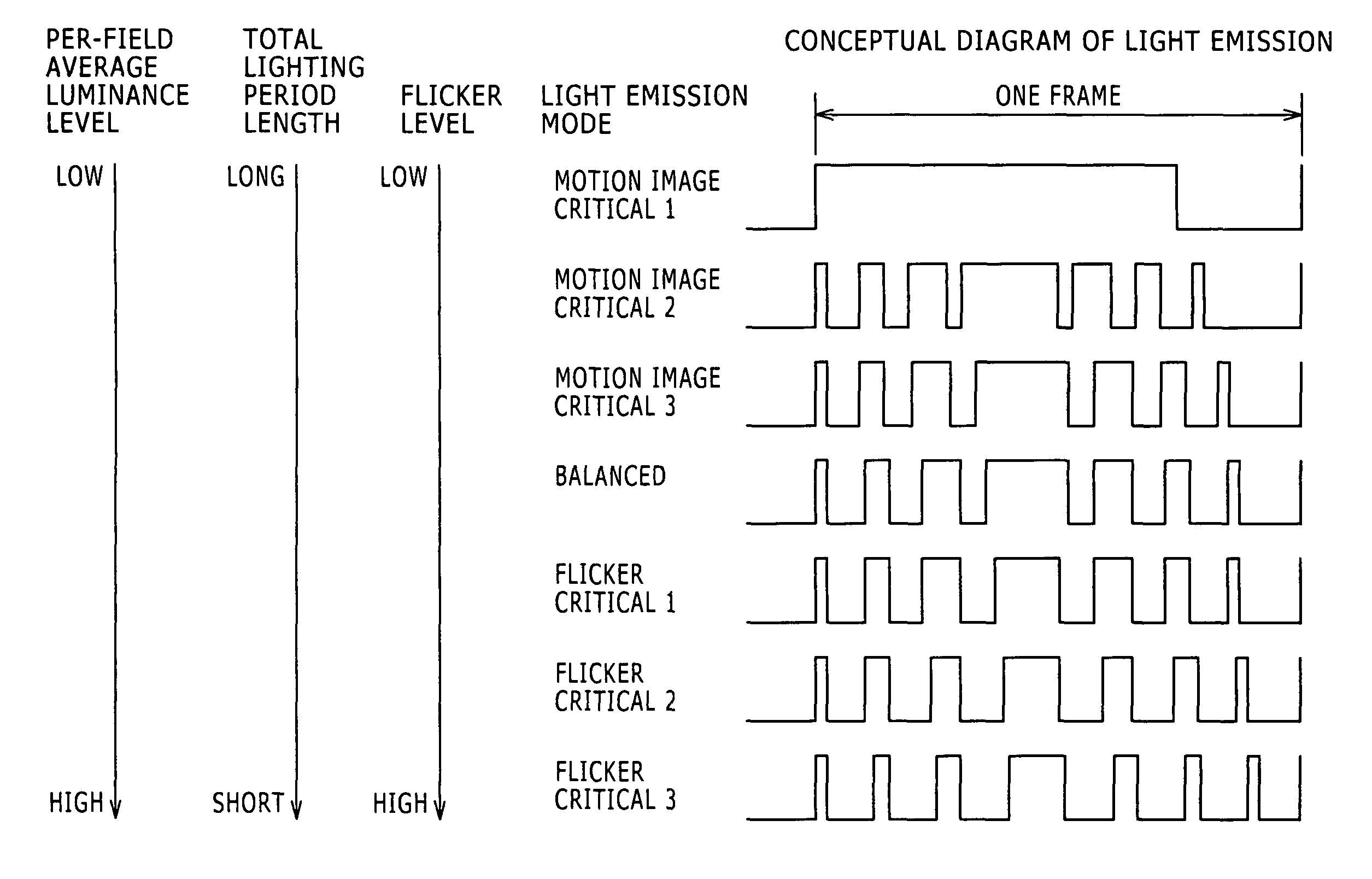
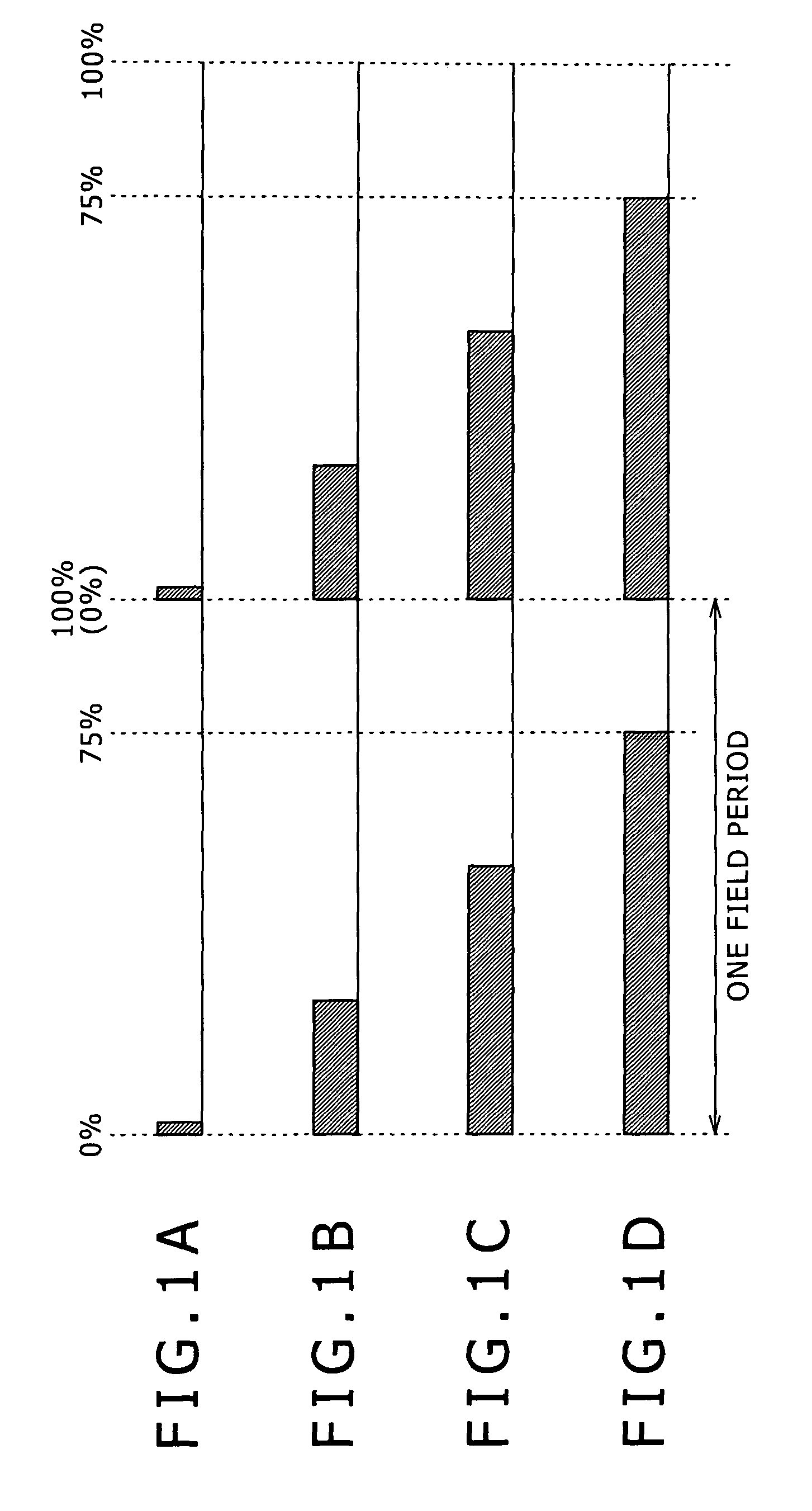
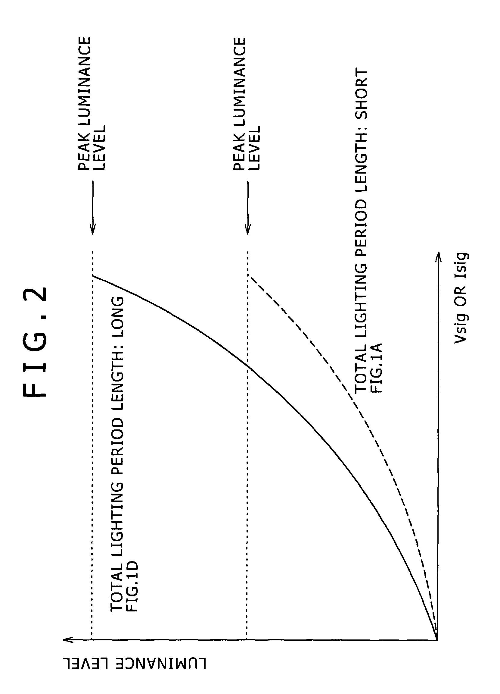
Disclosed herein is a lighting period setting method for a display panel which permits control of the peak luminance level by controlling the total lighting period length which is the sum of all lighting periods per field period, the lighting period setting method including the steps of, calculating the average luminance level across the screen based on input image data, determining light emission mode based on the calculated average luminance level, and setting the number, arrangement and lengths of lighting periods per field period according to the setting conditions defined for the determined light emission mode so as to provide the peak luminance level which is set according to the input image data.

Description

CROSS REFERENCES TO RELATED APPLICATIONS[0001]The present invention contains subject matter related to Japanese Patent Application JP 2008-032524 filed in the Japan Patent Office on Feb. 14, 2008, the entire contents of which being incorporated herein by reference.FIELD OF THE INVENTION[0002]The invention described in this specification relates to a technique for controlling the peak luminance level of a display panel.[0003]It should be noted that the invention has aspects of a lighting period setting method, display panel driving method, backlight driving method, lighting condition setting device, semiconductor device, display panel and electronic equipment.DESCRIPTION OF THE RELATED ART[0004]Liquid crystal panels have become widespread at a remarkable pace in recent years, finding application in a number of products. It should be noted, however, that these panels do not necessarily offer a fast motion image response speed. Therefore, today's liquid crystal panels incorporate count...

Claims


Application Information

Patent Timeline
Patent Type & Authority Patents(United States)
IPC IPC(8): G09G5/10G09G3/30G06F3/038G09G3/36
CPCG09G3/3233G09G3/3266G09G3/22G09G3/2022G09G3/3648G09G2300/0842G09G2300/0866G09G2320/0247G09G2320/0261G09G2320/0626G09G2320/064G09G2320/0646G09G2320/08G09G2320/103G09G2360/16G02F1/133G09G3/20G09G3/30G09G3/32G09G3/36
Inventor ISOBE, TEPPEIHASEGAWA, HIROSHIABE, HIRONOBU
Owner JOLED INC
Learn More