UTV gun mount system

a gun mount and utv technology, applied in the field of support structures, can solve the problems of threatening the safety of passengers, cumbersome and unsafe traditional gun racks that are currently available, and passengers' uncomfortably shifting,

Inactive Publication Date: 2013-05-21
BENNETT STEVE
View PDF13 Cites 34 Cited by
  • Summary
  • Abstract
  • Description
  • Claims
  • Application Information

AI Technical Summary

Benefits of technology

[0015]The first vertical long section of the first inverted L-shaped tubular member and the second vertical long section of the second inverted L-shaped tubular member may be partially inserted into receiving holes in side walls of a bed-box of a utility terrain vehicle. The first end of the first elastic cord is attached to the first hook which is situated at the first horizontal short section and the second end of the first elastic cord is connected to the utility terrain vehicle. The second elastic cord is attached to the second hook situated at the second horizontal short section and the second end of the second cable is connected to the utility terrain vehicle. The elastic cords thereby provide additional anchor points for securing the first inverted L-shaped tubular member and the second inverted L-shaped tubular member to the utility terrain vehicle.

Problems solved by technology

Unfortunately, many traditional gun racks that are currently available may be cumbersome and unsafe.
Many may take up space in the personal cabin of vehicles, causing passengers to shift uncomfortably to avoid the guns.
This also threatens the safety of passengers, as the guns or racks may strike them while vehicles are in motion.
Many gun racks may be difficult to install, and may not allow for efficient application and removal of guns.
Many gun racks and mounts comprise many parts, making it complicated to install or uninstall them from vehicles and to store them.

Method used


Image

  • UTV gun mount system
  • UTV gun mount system
  • UTV gun mount system

Examples


Embodiment Construction

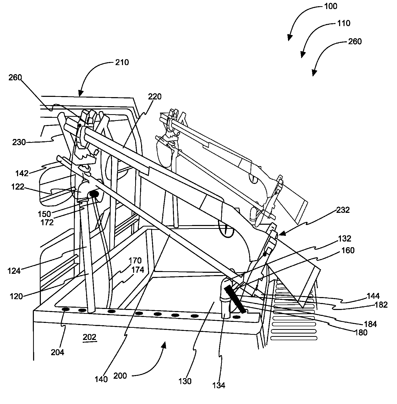
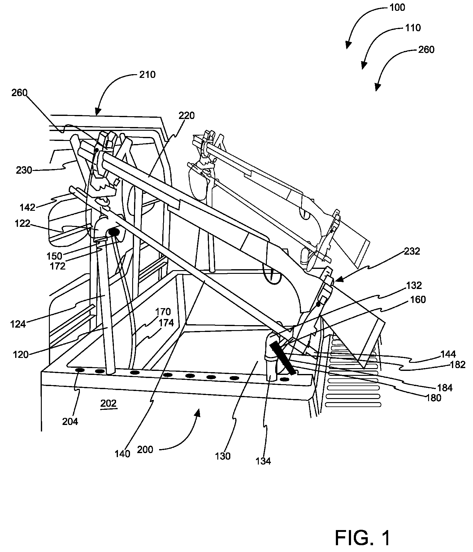
[0028]As discussed above, embodiments of the present invention relate to support structures for safely carrying weapons and more particularly to gun mounting apparatus for utility terrain vehicles 110 as used to safely transport weapons.

[0029]Referring to the drawings by numerals of reference there is shown in FIG. 1, a perspective view illustrating gun mounting apparatus for utility terrain vehicles 110 in ‘in-use’ condition 260 according to an embodiment of the present invention.

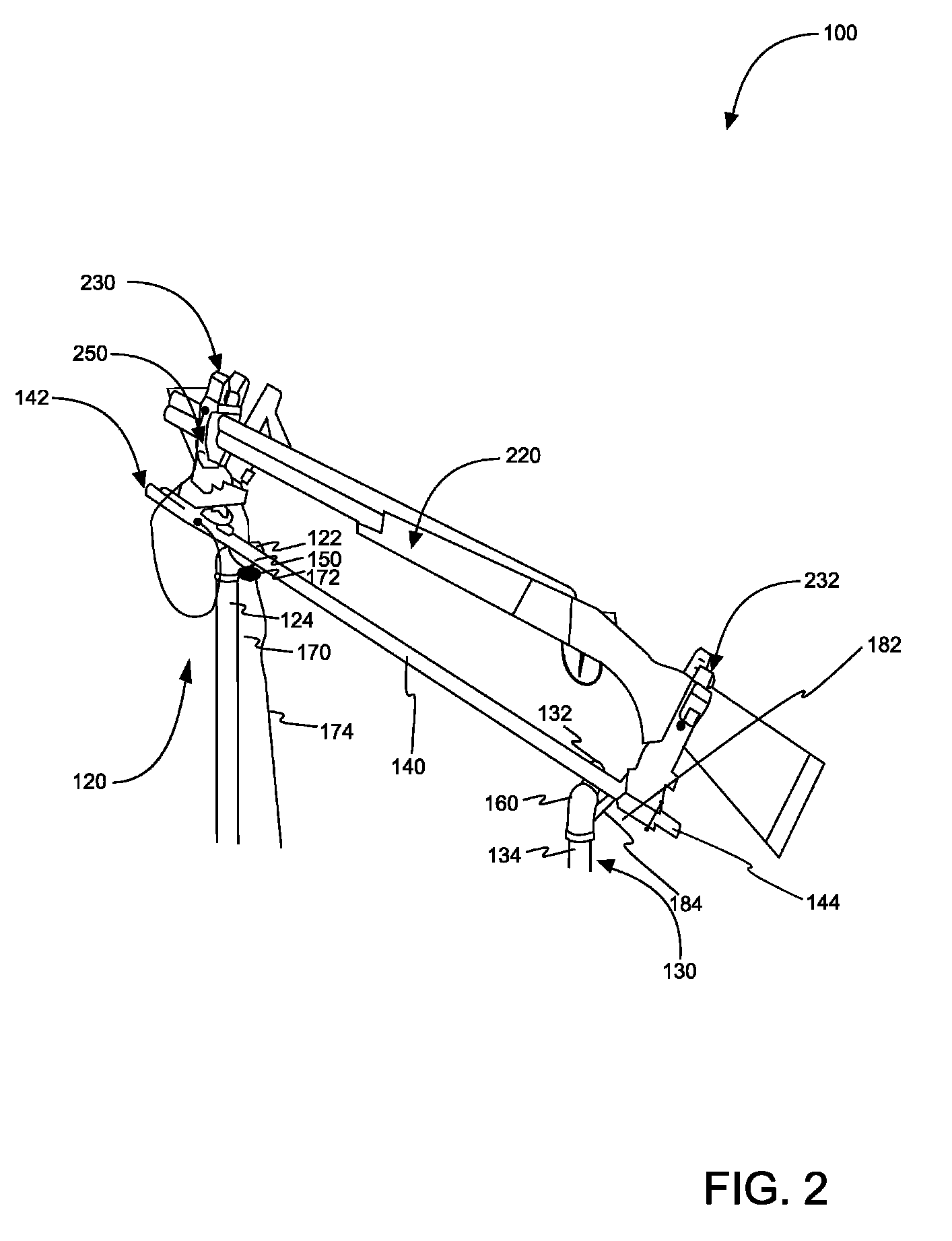
[0030]The present gun mounting apparatus for utility terrain vehicles 110 preferably comprises first inverted L-shaped tubular member 120 comprising first horizontal short section 122 and first vertical long section 124; second inverted L-shaped tubular member 130 comprising second horizontal short section 132 and second vertical long section 134; obliquely oriented tubular member 140 having a first tubular member end 142 and a second tubular member end 144; first attacher150 and second attacher 160 compri...


PUM


Abstract

A gun mounting apparatus for utility terrain vehicles comprising: a first inverted L-shaped tubular member comprising a first attacher, a second inverted L-shaped tubular member comprising a second attacher, an obliquely oriented tubular member having a first tubular member end and a second tubular member end with a gun grip attached to each tubular member end and a first elastic cord and a second elastic cord. The first and the second inverted L-shaped tubular member may be partially inserted into receiving holes in side walls of a bed-box of a utility terrain vehicle and may be additionally secured to the vehicle via the first and second elastic cord which are attached to the first and second attacher. The gun mounting apparatus for utility terrain vehicles is suitable for transporting at least one weapon securely fastened to the gun grips which are attached to the obliquely oriented tubular member.

Description

CROSS-REFERENCE TO RELATED APPLICATION[0001]The present application is related to and claims priority from prior provisional application Ser. No. 61 / 304,960, filed Feb. 16, 2010 which application is incorporated herein by reference.COPYRIGHT NOTICE[0002]A portion of the disclosure of this patent document contains material which is subject to copyright protection. The copyright owner has no objection to the facsimile reproduction by anyone of the patent document or the patent disclosure, as it appears in the Patent and Trademark Office patent file or records, but otherwise reserves all copyright rights whatsoever. 37 CFR 1.71(d).BACKGROUND OF THE INVENTION[0003]The following includes information that may be useful in understanding the present invention(s). It is not an admission that any of the information provided herein is prior art, or material, to the presently described or claimed inventions, or that any publication or document that is specifically or implicitly referenced is pr...

Claims


Application Information

Patent Timeline
Patent Type & Authority Patents(United States)
IPC IPC(8): B60R9/00
CPCB60R7/14F41A23/18
Inventor BENNETT, STEVE
Owner BENNETT STEVE
Why Eureka
Try Eureka