
Charger plate having illuminated members

a charger plate and illuminated technology, applied in the field of decorative charger plates, can solve the problems of inability to dynamically adapt and configure charger plates to color schemes, lightings, ambience, food types, etc., and achieve the effect of increasing the overall decorative nature of the table and enhancing the visual appearance of the charger pla

Inactive Publication Date: 2013-05-21
LEAL MARGO
View PDF11 Cites 10 Cited by
  • Summary
  • Abstract
  • Description
  • Claims
  • Application Information

AI Technical Summary

Benefits of technology

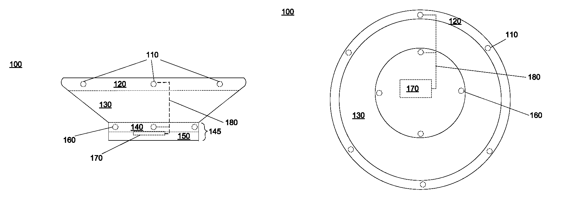
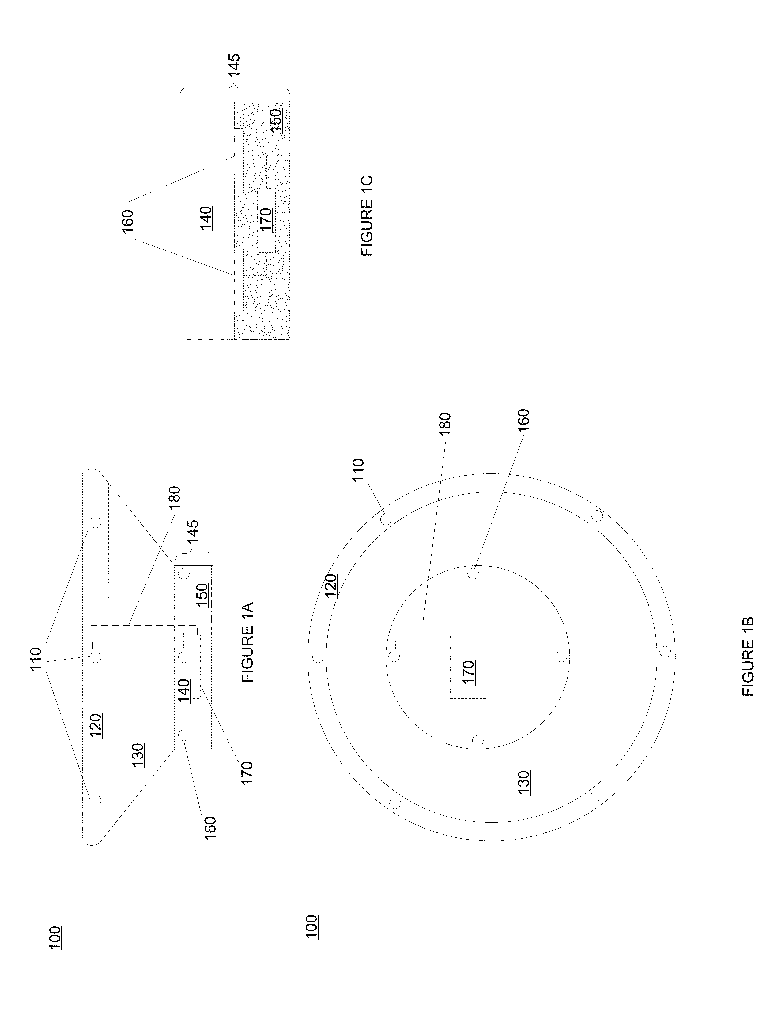
This patent describes a circuit that controls the operation of LEDs in a table setting. The circuit can change the color and brightness of the LEDs' light dynamically over time, and can turn each LED on / off in a desired sequence. The circuit can be powered by an external battery or power source, making it easier to hide from plain view. The charger plate includes a rim with LEDs, which can be controlled by the circuit. The LEDs can be powered by a wire placed underneath the raised portion of the charger plate. The patent aims to enhance the decorative nature of a table place-setting with the LEDs on the charger plate.

Problems solved by technology

Although charger plates improve aesthetic values, they nevertheless are limited to their fixed aesthetic and decorative features.
For example, charger plates are incapable of being dynamically adapted and configured to color schemes, lightings, ambience, types of food, etc.

Method used


Image

  • Charger plate having illuminated members
  • Charger plate having illuminated members
  • Charger plate having illuminated members

Examples


Embodiment Construction

[0022]Reference will now be made in detail to embodiments of the present invention, examples of which are illustrated in the accompanying drawings. While the invention will be described in conjunction with these embodiments, it will be understood that they are not intended to limit the invention to these embodiments. On the contrary, the invention is intended to cover alternatives, modifications and equivalents, which may be included within the spirit and scope of the invention as defined by the appended claims. Furthermore, in the following detailed description of the present invention, numerous specific details are set forth in order to provide a thorough understanding of the present invention. However, it will be evident to one of ordinary skill in the art that the present invention may be practiced without these specific details. In other instances, well known methods, procedures, components, and circuits have not been described in detail as not to unnecessarily obscure aspects ...


PUM


Abstract

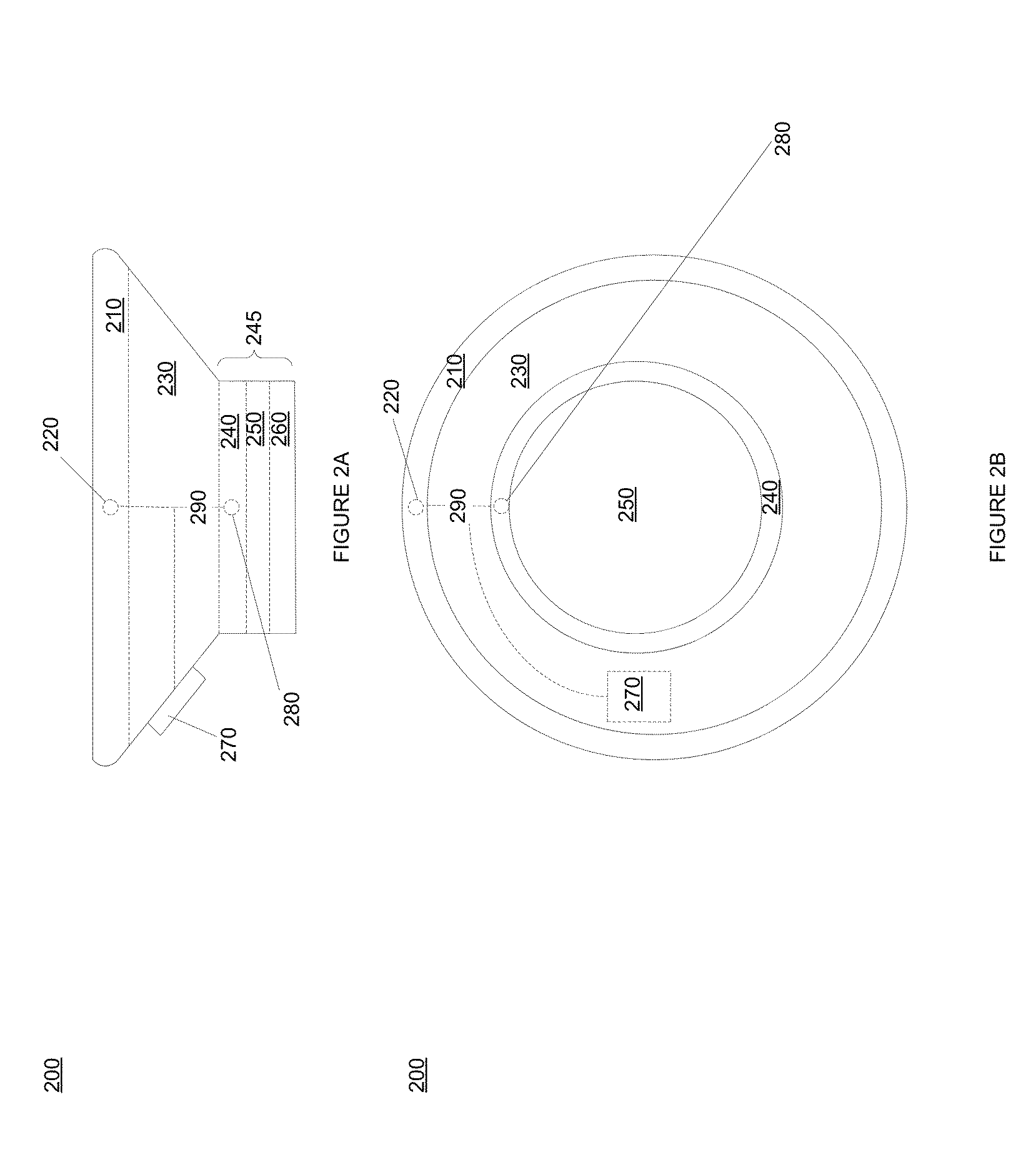
A charger plate having illuminated members. The charger plate includes a base, a raised portion, a rim and a circuit. The base is positioned substantially at a center of the charger plate and includes a first plurality of light emitting sources (LES) that outputs light from the base. The raised portion is substantially opaque and circumferentially surrounds the base. The rim circumferentially surrounds the raised portion and includes a second plurality of LES that outputs light from the rim. The circuit may independently control color and brightness associated with the first plurality of LES and the second plurality of LES. The base may include a reflective portion operable to reflect light from the first plurality of LES. The base and the rim may include a light pipe each for distributing the light emitted from their respective LES. The circuit may be powered via power inductive magnets instead of a battery.

Description

TECHNICAL FIELD[0001]The embodiments of the present invention relate to decorative charger plates.BACKGROUND ART[0002]In recent years, dining has become more than just food. For example, the ambience, the lighting, the food decoration, the music, the color coordination, etc., have become indispensable elements of most high-end establishments. To that end, the use of charger plates has increased for decorative purposes in order to improve aesthetic value and visual appeal.[0003]For example, charger plates are often used to decorate dinner tables at parties, weddings and other events. Usually, charger plates are left on the table as large coasters for soup, salad, appetizer, etc.[0004]Although charger plates improve aesthetic values, they nevertheless are limited to their fixed aesthetic and decorative features. For example, charger plates are incapable of being dynamically adapted and configured to color schemes, lightings, ambience, types of food, etc.SUMMARY[0005]Accordingly, a nee...

Claims


Application Information

Patent Timeline
Patent Type & Authority Patents(United States)
IPC IPC(8): F21V33/00
CPCF21V33/00F21V33/0036F21V23/003F21Y2101/02F21W2121/00F21Y2115/10
Inventor LEAL, MARGO
Owner LEAL MARGO
Learn More